
Installation and Maintenance Manual


32 VRF-SVN33A-EN
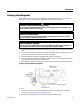
Insulating Refrigerant Pipes
Insulating Refrigerant Pipes
After determining that there are no leaks in the refrigerant pipes, insulate them as described:
1. Use Table 14 to select the insulation thickness according to pipe size and humidity conditions.
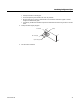
2. Wrap insulation around the entire surface of each pipe, including the refrigerant pipes from the
indoor unit to the service valves inside the outdoor unit, the branch joints, distribution header,
and connection points on each pipe.
Note: For details on insulating branch joints, refer to the branch joint installation manual (VRF-
SVN41).
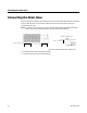
• Do not wrap the gas and liquid refrigerant pipes together.
• If gas and liquid pipes are in contact with one another, use thicker insulation and make sure
the pipes are not pressing tightly against one another.
• Pipe connections between the indoor unit and EEV kit: Leave 3/8 in. (10 mm) of space
between gas and liquid side pipes.
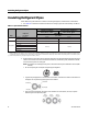
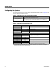
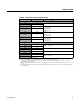
Table 14. Pipe insulation selector
Pipe
Pipe size
in. (mm)
Insulation Type
Standard conditions
86°F (30°C), < 85%
High humidity conditions
(a)
86°F (30°C), 85%
EPDM or NBR
(in. (mm)
Liquid pipe
1/4 (6.35) – 3/8 (9.52) 3/8 (9) 3/8 (9)
1/2 (12.70) – 2 (50.80) 1/2 (13) 1/2 (13)
Gas pipe
(b)
1/4 (6.35) 1/2 (13) 3/4 (19)
3/8 (9.52)
3/4 (19) 1.0 (25)
1/2 (12.70)
5/8 (15.88)
3/4 (19.05)
7/8 (22.23)
(a) When installing insulation in any of the following environments, use insulation required for high humidity conditions: Buildings with close proximity to
bodies of water or hot springs or on the side of a hill in which the building is partly covered by earth; ceilings frequently exposed to moisture such as
in restaurants, saunas, swimming pools, and corridors of dormitories or studios near a frequently-used outdoor exit; buildings with no ventilation system.
(b) Internal temperature of gas pipe is higher than 248°F (120°C).
Insulation
Insulation
Gas pipe
Liquid pipe
3/8 in.
(10 mm)
3/8 in.
(10 mm)
3/8 in.
(10 mm)