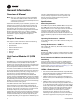
Installation, Operation, and Maintenance VAV-UCM 4.2 SAFETY WARNING Only qualified personnel should install and service the equipment. The installation, starting up, and servicing of heating, ventilating, and airconditioning equipment can be hazardous and requires specific knowledge and training. Improperly installed, adjusted or altered equipment by an unqualified person could result in death or serious injury.
Introduction Read this manual thoroughly before operating or servicing this unit. Warnings, Cautions, and Notices Safety advisories appear throughout this manual as required.Your personal safety and the proper operation of this machine depend upon the strict observance of these precautions. The three types of advisories are defined as follows: Indicates a potentially hazardous situation which, if not avoided, could result in death or serious injury.
Introduction Copyright This document and the information in it are the property of Trane, and may not be used or reproduced in whole or in part without written permission.Trane reserves the right to revise this publication at any time, and to make changes to its content without obligation to notify any person of such revision or change. Trademarks VariTrac, VariTrane,Trane and theTrane logo are trademarks or registered trademarks ofTrane in the United States and other countries.
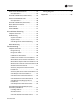
Table of Contents Introduction . . . . . . . . . . . . . . . . . . . . . . . . . . . . . 2 Warnings, Cautions, and Notices . . . . . . . . 2 Choosing a Location for Mounting the Sensor . . . . . . . . . . . . . . . . . . . . . . . . . .18 Important Environmental Concerns . . . . . 2 Setting the Rotary Address Switches on the Receiver and the Sensor . . . . . . . .19 Important Responsible Refrigerant Practices . . . . . . . . . . . . . . . . . . . . . . . . . . . 2 General Information . . . . . . . . .
Parallel Fan-Powered Units . . . . . . . . . . . . 39 Wiring Diagrams . . . . . . . . . . . . . . . . . . . . . .58 Occupied Units . . . . . . . . . . . . . . . . . . . . . 39 Appendix . . . . . . . . . . . . . . . . . . . . . . . . . . . . . . .66 Override Conditions (Parallel Fans) . . . . . 39 Series Fan-Powered Units . . . . . . . . . . . . . 40 Occupied Units . . . . . . . . . . . . . . . . . . . . . 40 Override Conditions (Series Fan) . . . . . . . 40 Zone Sensor Functions . . . . . . . . . . . .
General Information Overview of Manual Note: One copy of the document is shipped with VAV units that have UCM 4.2 DDC controllers and is customer property. It must be retained by the unit's maintenance personnel. This booklet describes proper installation, operation, and maintenance procedures for delivered air systems. By carefully reviewing the information within this manual and following the instructions, the risk of improper operation and/or component damage will be minimized.
General Information • UCM 4.2 adds a binary 24VAC, dry contact input. It can be configured either as a generic input or as an occupancy detector input. • UCM 4.2 adds a VariTrac Bypass Damper mode of operation. In this mode, supply air temperature and supply air pressure is made available on the Comm4 link.The damper position is a Comm4-control parameter. A Comm4 configurable failsafe position was added.The supply air temperature uses a new "S" input (TB3-7).
General Information Water Heat Output Configuration UCMs that have hot water heat outputs can be configured for normally open or normally closed. Zone Sensor Functions Zone sensor functions now include: air valve drive to maximum, use unoccupied set points, timed override, and cancel timed override. Slaving of Zone Sensors Up to three (3) UCM 4.2 may be connected to a single zone sensor. Generic UCM Capability UCM 4.2 can be configured to control non-Trane VAV boxes.
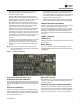
VAV Start Up/Check Out Procedure Chapter Overview Table 1. LED State This chapter contains information about the following: • Unit 4.2 Pre-Power Check-Out • Light Emitting Diode (LED) Operations • Zone Sensor Check-Out UCM 4.2 Pre-Power Check-Out Green LED power function indication Indication "On” Board functioning correctly Blinking Board malfunction (Replace Board) "Off” Board does not have power The yellow LED functions as the communication indicator.
VAV Start Up/Check Out Procedure Zone Sensor Check-out If an erroneous temperature is being reported to the UCM, use the “Zone sensor temperature-resistance table,” p. 10 to verify the integrity of the adjustable set point potentiometer or sensor.The resistance should be measured across the terminals to which the device is connected. Note: Disconnect the zone sensor from the UCM when making the checks listed in the table below. Table 3.
UCM 4.2 Installation and Wiring WARNING Hazardous Voltage! Disconnect all electric power, including remote disconnects before servicing. Follow proper lockout/ tagout procedures to ensure the power can not be inadvertently energized. Failure to disconnect power before servicing could result in death or serious injury. UCM power requirement, add the power consumption per stage to the circuit board power requirement.
UCM 4.2 Installation and Wiring route zone sensor wires in conduit with 24VAC or other high power conducting wires. Multiple UCM’s Per Zone Sensor Up to three (3) UCM’s may be connected to a single zone sensor and thumbwheel set point. • Connect terminal connectionsTB3-1,TB3-2, andTB33 in parallel (i.e. daisy chain) from the master UCM to the slaved UCM(s). Zone Sensor The wireless zone sensor with night setback timed override (TOV) on/cancel button.
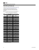
UCM 4.2 Installation and Wiring 2. The maximum wire length should not exceed 5,000 feet (1,524 m). 3. Communication link wiring cannot pass between buildings. Table 6. DIP switch settings for UCM 4.2 (continued) UCM Unit # Address Dip 1 2 3 4 5 6 OFF ON ON OFF ON ON ON 9 73 4. A maximum of 63 UCMs can be connected to each COM Link. Daisy chaining is a typical configuration. “STAR” chaining is also acceptable.
UCM 4.2 Installation and Wiring Table 6. DIP switch settings for UCM 4.2 (continued) Dip UCM Unit # Address 1 2 3 4 5 6 ON OFF OFF OFF OFF 60 124 ON 61 125 OFF ON OFF OFF OFF OFF 62 126 ON OFF OFF OFF OFF OFF 63 127 OFF OFF OFF OFF OFF OFF The following figures show wiring diagrams for typical applications of UCM 4.2 . Wiring diagram for single duct units with factory installed electric reheat HEATER STAGE CONTACTOR(S) OPTIONAL TRANSFORMER 9.
UCM 4.2 Installation and Wiring Figure 4.
UCM 4.2 Installation and Wiring Figure 5.
Wireless Zone Sensor Overview TheTrane Wireless Zone Sensor set includes a sensor and a receiver that work together to provide the same functions as the equivalentTrane wired sensor (#41901090), such as the standard 10 k temperature input (with the exception of the communication jack). No further software or hardware is necessary for site evaluation, installation, or maintenance. The sensor transmits the zone temperature, all zone temperature setpoint functions, timed override Occupied Figure 6.
Wireless Zone Sensor Figure 7. Mounting hole dimensions for sensor 3.27 in (8.30 cm) 2.36 in (6.00 cm) 1.34 in (3.41 cm) Note: The dimensions are the same for both the sensor and the receiver.
Wireless Zone Sensor Ambient considerations • Avoid placing the sensor inside metal enclosures Avoid locations that are outside the operating temperature and humidity range (see Table 14, p. 48). • Avoid radio transmissions through thick, solid concrete walls Location Considerations for the Sensor Setting the Rotary Address Switches on the Receiver and the Sensor When selecting a location for the sensor, consider both thermal and radio transmission characteristics of the location.
Wireless Zone Sensor Setting the Sensor Address 1. Using a small screwdriver, set the three rotary address switches (locations S1, S2, S3) on the sensor (Figure 8, p. 19) to the same address used for the receiver it is to be associated with. 2. Make a notation of the address and location where this sensor is to be mounted. Note: Do not use 000 as an address for installation. If you set the address to 000, it will: – Remove all association knowledge – Revert to a low-power hibernation mode.
Wireless Zone Sensor Figure 9. Factory wiring of the receiver to the VAV UCM W (HOT) TO J8 PROP. WATER VALVE 24VAC 12VA MAX BK (CLOSE) TO J9 R (OPEN) TO J10 BL 24VAC 60HZ NEC CLASS-2 CONTROL CIRCUIT LOAD= 12VA (WITHOUT HEAT) DAMPER ACTUATOR WIRING OPTIONAL FIELD INSTALLED PROPORTIONAL WATER VALVE OPTIONAL FACTORY INSTALLED WIRELESS 8.
Wireless Zone Sensor Replacing and Securing the Receiver Cover Figure 11. LED5 stays on after applying power to the receiver 1. To replace the receiver cover on the base plate, hook the cover over the top of the base plate. Apply light pressure to the bottom of the cover until it snaps in place. 2. If necessary to keep the cover securely attached, install the security screw into the bottom of the receiver (Figure 10, p. 22). Figure 10.
Wireless Zone Sensor Powering the Sensor and Associating the Sensor to the Receiver 2. View LED1, LED2, and LED3 to determine the strength of the signal. View LED5 to determine the strength of the battery. 1. Verify the sensor is set to the same address as the associated receiver. 2. Remove the insulation barrier, which is a plastic strip located between the two batteries (Figure 13, p. 23). 3. Association will automatically occur between the sensor and the receiver.
UCM Programming and Operation Chapter Overview This chapter contains information about the following: • Accessing Rover/Comm4 • UCM HomeTabs: At a Glance • UCM HomeTabs: Instructions • Entering and Exiting the Service Mode • Overriding VAVs • Resetting Diagnostics Note: For Instructions on how to use Rover Comm4, refer to the Rover Comm4 online Help by clicking Contents and Index on the Help menu.
UCM Programming and Operation Figure 16. Connecting to a Comm4 controller using alligator clips 4. Double-click on the Comm4 Service Tool icon to access a Comm4VAV UCM.This tool allows the user to monitor, configure, and test Comm4. Figure 17. Rover service tool Comm4 PCMCIA card Black Red Adapter cable RJ11 plug 3. Double-click the Rover icon on the laptop PC desktop. The Rover Service Tool screen will appear. 5. Rover/Comm4 will launch. Click to launch the Scan for Devices dialog box. Figure 18.
UCM Programming and Operation 6. The user may search by the address of a single UCM or scan the range of UCM addresses specified Note: Address for VAV UCM's range from 65-127. 7. Select the desired device or range of devices and click the Scan button.You’ll be able to watch as the applications scan for the selected data. 8. Once the scan is complete, the results will populate the device tree on the left-hand side of the Rover/Comm4 screen. Figure 20.
UCM Programming and Operation Status Tab Unit Info UnitType:The different types of units for the selected UCM. unit's airflow rate is less than 5% or greater than 110% of the unit's cataloged CFM. For example, the UCM will use position control for a size 600 CFM unit if the flow is less than 30 CFM (5%) or greater than 660 CFM (110%). Note: Although the UCM will read flow down to 5% of cataloged and up to 110% of cataloged, the range of MIN FLOW settings is 0%, or 10% to 100% of cataloged.
UCM Programming and Operation Wireless Tab Note: This tab displays the older style wireless not to be confused with the new wireless that is being currently offered. configured as not present then the hardwired setpoint sensor failure flag will not be set as long as at least one wireless sensor is transmitting a valid setpoint. Advanced Configuration Tab When the UCM version is 3.0 or higher, this tab displays the wireless sensor serial number assignments.
UCM Programming and Operation In Rover, the setpoints can be viewed at the UCM Setpoints tab and then also changed by selecting the Configure button. Following are descriptions of each line on the UCM Setpoints tab. UCM's active cooling set point during occupied times. The cooling set point must be greater than or equal to the heating set point plus 2.0°F (1.1°C).
UCM Programming and Operation Maximum Flow must be greater than or equal to the entry in any of the Minimum fields. Min Heating:The UCM will not drive its position/flow below this value under normal operating conditions while in the HEAT mode (warm air in the supply duct) or while it is using local heat.The Min Heating Flow value must be less than or equal to the Maximum Flow value.
UCM Programming and Operation Other Fields Unit Type: Select the proper unit type.The unit type information is maintained in the controller's EEPROM. Important: Edit the unit type BEFORE editing any items on the above list! Unit types available for all versions: • VariTrane C • VariTrac - Round • VariTrane D • Generic Unit types available for VAV version 4.
UCM Programming and Operation BIP Configuration: Version 4.0 or higher UCMs are provided with a binary input that can be used to monitor either an occupancy sensor or provide the status of a generic binary input. Valid Selections: Occupancy, Generic. BIP Configuration default is Generic.The BIP Configuration interface is for dry relay contacts connected toTB4-1. In generic mode, the state of the input is only passed on from the UCM to Summit.
UCM Programming and Operation Note: Set point vote determines the weighting of the set point vote.The range is 0-9.This number represents the number of votes the sensor gets when the set points are averaged. If "0" is selected the sensor gets no vote. Wired Thumbwheel Select the check box to enable the local thumbwheel setpoint input.
UCM Programming and Operation Advanced Configuration Tab Figure 26. Advanced configuration tab Air Valve/Damper Drive time:This adjustment can be used to match the DDC UCM 4.2 to the actuator drive time.The air valve damper actuator drive time will be automatically adjusted to the type ofTrane Unit type selected. Min DriveTime: Displays the minimum time that the output can be driven.This value restricts the change in the mechanical output.
UCM Programming and Operation Entering and Exiting the Service Mode Controllers must be online and in the service mode to receive an override.The service mode disables control fromTracer and places Rover/Comm4 in command of the controller. Controllers that are in the service mode appear in bold in the device tree on the left side of your screen. More than one controller can be in the service mode at one time.
UCM Programming and Operation Figure 27. Configuration screen (save as) 2. Click the File menu and click Save As. 3. The Save As dialog box will appear. Name unit and click Save. Figure 28. Save As prompt Downloading Program Files from PC to DDC UCM 4.2 1.
UCM Programming and Operation Figure 29. Configuration screen (open) 2. Click the File menu and click Open. 4. Download to DDC VAV controller. 3. The Open dialog box will appear. Select the file you wish to open and click the Open button. 5. Program is now in controller. Figure 30.
Sequence of Operations Chapter Overview Override Conditions (Single Duct) This chapter contains information about the following: • Single Duct Units The UCM occupied controls can be overridden by the following override commands: • Override Conditions (Single Duct) Unoccupied • Fan-Powered Units • Parallel Fan-Powered Units • Override Conditions (Parallel Fans) • Series Fan-Powered Units If the control mode is unoccupied (either as edited by software or as determined by the binary input), the
Sequence of Operations Fan-Powered Units Table 10. Table 11. Stage point Fan actuation schedule FAN TYPE Series OCCUPIED UNOCCUPIED ON OFF if valve closed AND reheat off Cool mode: ON if zone temp
Sequence of Operations Recalibrate (Reset) • The recalibrate function can be enabled. Series Fan-Powered Units Air valve control for series fan-powered units is the same as both single duct and parallel fan-powered units. During the occupied mode of operation, the series fan is continuously energized. Heat stages are energized on the following schedule: Stage Heat Control Override Heat control can be disabled locking out heat outputs. Occupied Units Table 12. Drive Air Valve to Maximum Flow.
Sequence of Operations command. When a zone sensor thumbwheel is turned to its low limit, indicated by a “**” on the thumbwheel, and the ON button is pressed, the UCM will initiate a “Go UNOCCUPIED” command.The UCM will maintain the command until the zone sensor set point is adjusted to within the range of 50° to 85°. Any zone sensor module that has a thumbwheel and ON (TOV) button can initiate these commands.
Air and Water Balancing Chapter Overview This chapter contains information about the following: • Air Balancing • Water Balancing set point until the zone sensor knob is moved back into the normal operating range. 7. Read airflow at the most remote unit. In most systems, this will be the VAV unit located furthest from the fan. This will be the unit in the system that will be critical from an air delivery set point. If airflow is not adequate, increase the supply fan CFM to achieve adequate airflow.
Air and Water Balancing Figure 31. Measured value field If reported flow in Rover is different from the measured CFM (flow hood measurement) a cooling flow correction can be calculated by Rover by entering the measured flow in the measured value field. See above, Figure 31, p. 43. Figure 32.
Air and Water Balancing 1. Adjust eachVAV box maximum flow set point required for its zone using the UCM set points menu. See Figure 32, p. 43. 3. Continue to the next group/box repeating VAV unit air balancing procedures until each unit is delivering the correct CFM. Note: This could already be done in the factory in its commissioning process. 4. Upon completion of the VAV air balancing, remove all overrides. 2. After balancing a group/box, return that group/box flow override to AUTO. 5.
Troubleshooting • DiagnosticTable WARNING Live Electrical Components! During installation, testing, servicing and troubleshooting of this product, it may be necessary to work with live electrical components. Have a qualified licensed electrician or other individual who has been properly trained in handling live electrical components perform these tasks. Failure to follow all electrical safety precautions when exposed to live electrical components could result in death or serious injury.
Troubleshooting Figure 35. Items reported Diagnostic Table Table 13. Sensed Parameter Use the DiagnosticTable (Table 13, p. 46) for failure parameters and Comm. 4 UCM actions to help understand issue. Table 13. Failure Criteria Open OR Short (> 25 Zone Temperature seconds) AND no active wireless sensors. Thumbwheel Setpoint Air Flow Action Taken CO(a) If failed open, control valve as if very cold temperature. If failed shorted, control as if very hot temperature.
Troubleshooting • The green LED indicates power and should be "steady" ON. • Measure the power input toTB1-1 (power) andTB1-2 (ground) of the UCM board.The supply voltage should be between 20 and 28 VAC (24 VAC cataloged). However, voltages at either extreme may result in system instability. • If no voltage, check up stream of controller to see were voltage has been interrupted. See complete wiring diagrams, Figure 44 to Figure 51.
Troubleshooting wires that were connected to terminals 1 and 2 of zone sensor.You should measure 5VDC. If you do not have 5VDC then see if the VAV UCM is outputting 5VDC.This can be done by disconnecting the wires on the VAV UCM on terminalsTB3-1 andTB3-2 and measure the VDC. It should be 5VDC. If you have 5VDC at the UCM the wires going to the zone have an open. If 5VDC is not present check incoming power to the UCM board on TB1-1 andTB1-2. Should measure 24 VAC ± 10%.
Troubleshooting • Cut jumper wires (W1 and W2) on all slave units. If jumper is not cut it will give erroneous temperature setpoint value. Wireless Zone Sensor Failure Procedures In the event that the UCM reports an incorrect zone Temperature/sepoint, properly inspect the following: Note: No special tools or software are necessary to service and test the wireless zone sensor system.
Troubleshooting • Press theTest button (S5) on the sensor. LED5 should turn On solid green, indicating proper battery strength. LED1, LED2, and LED3 will indicate signal strength (See table 2). Table 18.
Troubleshooting Table 20. measure the proper voltage atTB1-1 andTB1-2 and no voltage atTB3-1andTB3-2 replace UCM. Receiver resistance table (continued) Zone or Setpoint Temperature Nominal Zone Temperature Output Resistance Nominal Space Temperature Setpoint Output Resistance 75 oF (23.9 oC) 10.5 k Ω 403 Ω 80 oF (26.7 oC) 9.3 k Ω 305 Ω 85 oF (29.4 oC) 8.
Troubleshooting • Check to see if flow has been established, If flow not established or inaccurate proceed to Step 2. • Rover software will indicate that calibration is taking place in diagnostic log • When calibration is complete, the box will release to auto. Drive the box open to make sure that the box is not below 5% of its cataloged CFM.The controller is accurate in reading flow from 5% to 110% of cataloged CFM. 2. The tubing or flow ring is off, reversed, plugged, or has a leak.
Troubleshooting Auxiliary Temperature Sensor Failure Procedures In the event that the UCM reports an incorrect or failed Auxiliary temperature, properly inspect the following: 1. Make sure VAV UCM has been configured for auxiliary input Figure 40. UCM setup screen Should measure 24 VAC ± 10%. If proper voltage measured onTB1-1 andTB1-2 and no voltage at TB3-1 andTB3-2 replace UCM. Note: If no voltage atTB3-5 andTB3-6 see UCM see UCM failure procedures. 6.
Troubleshooting • UCM is going through a recalibrate (reset) command.This is shown in the diagnostic log in Rover • Wait for calibration to finish. 2. Zone temperature is greater than the heat set point or less than the cool set point • Change the heat and/or cool set points. 3. Actuator not driving full drive time • Drive time in advanced configuration not set at 90 seconds on current VariTrane units or 60 seconds for varitrac units • Adjust to correct damper travel time using Rover software.
Troubleshooting TB1-2 (ground) of the UCM board.The supply voltage should be between 20 and 28 VAC (24 VAC cataloged). However, voltages at either extreme may result in system instability. • Triac can be checked with purchasing a 24 VAC LED and see if it lights up on call for fan UCM if LED does not light up replace UCM. • Remove fan wires from UCM and apply 24 VAC directly. • Fan relay should energize. If it does not check wiring. If wiring is OK replace fan relay Figure 42.
Troubleshooting • Measure the power input to 24 VAC terminal and Common/ground terminal of the ECM board.The supply voltage should be between 19.2 and 28.2 VAC (24 VAC cataloged). However, voltages at either extreme may result in system instability. • If low or no voltage, check up stream of controller to see how voltage has been interrupted. See complete wiring diagrams (Figure 50, p. 64 and Figure 51, p. 65). 2.
Troubleshooting • Check J8 toTB1-2. Should have 24VAC; if it does not if not measure the power input toTB1-1 (power) and TB1-2 (ground) of the UCM board.The supply voltage should be between 20 and 28 VAC (24 VAC cataloged). However, voltages at either extreme may result in system instability. • HeatTriac(s) can be checked with purchasing a 24 VAC LED and see if it lights up on call for Heat output to be open or closed by UCM. If LED does not light up replace UCM.
Troubleshooting Wiring Diagrams Figure 44. Wiring diagram for single duct unit that is either cooling only, hot water, or field installed reheat W (HOT) TO J8 PROP. WATER VALVE 24VAC 12VA MAX BK (CLOSE) TO J9 R (OPEN) TO J10 BL 24VAC 60HZ NEC CLASS-2 CONTROL CIRCUIT LOAD= 12VA (WITHOUT HEAT) DAMPER ACTUATOR WIRING OPTIONAL FIELD INSTALLED PROPORTIONAL WATER VALVE OPTIONAL FACTORY INSTALLED WIRELESS 8.
Troubleshooting Figure 45. Wiring diagram for fan powered unit that is either cooling only, hot water, or field installed reheat W (HOT) TO J8 R (OPEN) TO J10 BL DAMPER ACTUATOR WIRING PROP.
Troubleshooting Figure 46.
Troubleshooting Figure 47.
Troubleshooting Figure 48.
Troubleshooting Figure 49.
Troubleshooting Figure 50.
Troubleshooting Figure 51.
Appendix AC AHU AIP Analog Input AOP Analog Output AVG Average AWG American Wire Gauge BCU Building Control Unit BIP Binary Input BMS Building Management System BOP Binary Output oC Celsius CCP Central Control Panel CFM Cubic Feet per Minute CMS Cubic Meters per Second CO2 Carbon Dioxide COM Communication CPL Custom Program Language CU Command Unit DDC Direct Digital Control DEG Degree DP EEPROM Differential Pressure Electrically Erasable Programmable Read Only Memory o
Trane optimizes the performance of homes and buildings around the world. A business of Ingersoll Rand, the leader in creating and sustaining safe, comfortable and energy efficient environments, Trane offers a broad portfolio of advanced controls and HVAC systems, comprehensive building services, and parts. For more information, visit www.Trane.com. Trane has a policy of continuous product and product data improvement and reserves the right to change design and specifications without notice.