
Installation and Maintenance Manual


Troubleshooting
VAV-SVX01D-EN 51
• When the test is complete, reset the receiver
address to its previous setting.
• Press theTest button (S5) on the sensor to force re-
association.
Confirm association and communication by noting LED1,
LED2, and LED3 as described in "Signal QualityTest"
• Pressing theTest button (S5) on the sensor initiates
a signal quality test. LED1, LED2, and LED3 respond
by indicating excellent, marginal, or poor signal
quality.The LEDs can be observed on both the
sensor (Table 21, p. 51) and the receiver (Table 20,
p. 50).
• If sensor and receiver still do not operate properly,
replace bad components. If unit passes tests, check
UCM operation.
4. Defective VAV UCM
• Disconnect the receiver sensor wires on the VAV
UCM on terminalsTB3-1 andTB3-2 and measure
the VDC. It should be 5VDC. If 5VDC is not present
check incoming power to the UCM board onTB1-1
andTB1-2. Should measure 24 VAC ± 10%. If you
measure the proper voltage atTB1-1 andTB1-2 and
no voltage atTB3-1andTB3-2 replace UCM.
Note: If no voltage atTB1-1 andTB1-2 see UCM
see UCM failure procedures
• Disconnect the receiver sepoint wires on the VAV
UCM on terminalsTB3-2 andTB3-3 and measure
the VDC. It should be 5VDC. If 5VDC is not present
check incoming power to the UCM board onTB1-1
andTB1-2. Should measure 24 VAC ± 10%. If you
measure the proper voltage atTB1-1 andTB1-2 and
no voltage atTB3-2andTB3-3 replace UCM.
Note: If no voltage atTB1-1 andTB1-2 see UCM
see UCM failure procedures
Airflow Failure Procedures
In the event that the air valve is reading position instead of
flow or in the event that the measured flow reads
incorrectly, i.e. different from the balance report, properly
inspect the following:
• RecalibrateVAV unit by cycling power to unit.This can
also be accomplished with Rover, Summit or CCP
software.
Note: Cycling power to the VAV board will
automatically cause the unit to calibrate,
however, following the procedure outlined
below will provide a more accurate calibration.
It is only necessary to perform this procedure in
instances where you are experiencing incorrect
flow readings or if the unit reverts to pressure
dependent mode despite being above 5% and
below 110% of cataloged flow and performing a
"normal calibration") does not correct the
problem.
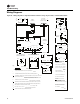
1. Steps for Calibration
• Log on to the UCM with Rover software.
• Turn the central air handler "off." If this is not
possible,Trane recommends pulling the transducer
tubes off during the calibration process to simulate
this.
• Select the "calibrate unit" option button
75
o
F (23.9
o
C) 10.5 k Ω 403 Ω
80
o
F (26.7
o
C) 9.3 k Ω 305 Ω
85
o
F (29.4
o
C) 8.25 k Ω 208 Ω
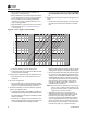
Table 21. Signal quality: LED1, LED2, LED3 on the sensor
User
Action LED Display Indicates…
None
LED1:Off
LED2:Off
LED3:Off
Normal state
* No Test button press
Press Test
Button
(SS)
LED1:Off
LED2:Off
LED3:Off
Associated; no communication with
receiver
* Associated, but no signal from the
receiver after pressing Test button
LED1:On
LED2:On
LED3:On
Displays for 5
seconds, then
constantly off
Excellence signal quality
* Adequate signal margin for reliable
communication.
LED1:Off
LED2:On
LED3:On
Displays for 5
seconds, then
constantly off
Marginal signal quality
* Reduced battery life is likely.
* Consider moving the sensor or
receiver to a better location.
LED1:Off
LED2:Off
LED3:On
Displays for 5
seconds, then
constantly off
Poor signal quality
* Unreliable communication.
* Strongly recommend moving the
sensor or receiver to a better location.
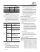
Table 20. Receiver resistance table (continued)
Zone or Setpoint
Temperature
Nominal Zone
Temperature
Output Resistance
Nominal Space
Temperature
Setpoint Output
Resistance
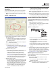
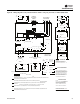
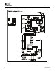
Figure 38. Rover software