Installation Operation Programming VAV VV550 LonTalk Controller May 2010 VAV-SVP01A-EN
Warnings, Cautions and Notices Warnings, Cautions and Notices. Note that warnings, cautions and notices appear at appropriate intervals throughout this manual. Warnings are provided to alert installing contractors to potential hazards that could result in personal injury or death. Cautions are designed to alert personnel to hazardous situations that could result in personal injury, while notices indicate a situation that could result in equipment or property-damage-only accidents.
Warnings, Cautions and Notices WARNING Electrocution and Fire Hazards with Improperly Installed and Grounded Field Wiring! Improperly installed and grounded field wiring poses FIRE & ELECTROCUTION hazards. To avoid these hazards, you MUST follow requirements for field wiring installation and grounding as described in NEC and your local/state electrical codes. All field wiring MUST be performed by qualified personnel. Failure to follow these requirements could result in death or serious injury.
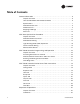
Table of Contents General Information . . . . . . . . . . . . . . . . . . . . . . . . . . . . . . . . . . . . . . . . . . . . . . . . . . . . 6 Chapter Overview . . . . . . . . . . . . . . . . . . . . . . . . . . . . . . . . . . . . . . . . . . . . . . . . . . 6 Unit Control Module VAV VV550 Controller . . . . . . . . . . . . . . . . . . . . . . . . . . . 6 Specifications . . . . . . . . . . . . . . . . . . . . . . . . . . . . . . . . . . . . . . . . . . . . . . . . . . . . . 7 VV550 Enhancements . . . . .
Occupancy Modes . . . . . . . . . . . . . . . . . . . . . . . . . . . . . . . . . . . . . . . . . . . . . . . . 68 Space Temperature Control: Single Duct Units . . . . . . . . . . . . . . . . . . . . . . . . 69 Space Temperature Control: Fan-Powered Units . . . . . . . . . . . . . . . . . . . . . . 72 Ventilation Flow Control . . . . . . . . . . . . . . . . . . . . . . . . . . . . . . . . . . . . . . . . . . . 74 Flow Tracking . . . . . . . . . . . . . . . . . . . . . . . . . . . . . . . . . . . . . . . . .
General Information Chapter Overview This chapter contains information about the following: • Unit Control Module VAV VV550 Controller • Specifications • VAV VV550 Controller Enhancements • VAV VV550 Controller Features • Shipping & Storage • Data Lists Unit Control Module VAV VV550 Controller The VV550 is a microprocessor-based, Direct Digital Controller (DDC) for the (Variable Air Volume) VAV terminal unit.
General Information Specifications Power Requirements The UCM VV550 requires 18-32 Vac (24VAC nominal), 50/60 Hz, and up to 50 VA, depending on the number of heat outputs (stages), which consume 10 VA each.
General Information VV550 Enhancements Controller Interface Flexibility VV550 controller allows VAV units to communicate on a Trane Comm5 or LonTalk. This controller works in standalone mode, peer-to-peer with one or more other units, or when connected to a Trane Tracer Summit or a 3rd party building automation system that supports LonTalk. Manual Test Function The VV550 controller includes a manual test button that allows the field technician to manually exercise the outputs of the controller.
General Information Flash Download The VAV controller has been designed with flash memory. This allows us the option of upgrading the controller in the field (features, corrections to defects) without changing out the controller. Air/Water Balancing Application An air/water balancing application is available in Rover that simplifies the startup, checkout and balancing of VAV systems. This application is specifically designed for the balancing contractor.
General Information within system limits for outside air percent concentrations in the supply air stream. Until Tracer Summit v15, this feature was provided by way of field custom programming. CO2 Based Demand Control Ventilation As a part of the standard application, the VAV system has the ability to calculate the ventilation setpoint for the air-handling unit based on the CO2 in one or more spaces. Until Tracer Summit v15, this feature was provided by way of field custom programming.
General Information Figure 1. VV550 board layout VAV VV550 controller and VAV 4.2 controller comparisons VAV VV550 Supports Comm5 VAV 4.2 Supports only Comm4 or Comm3 (VariTrac or VariTrane) No local CO2 sensor input. Uses only a communicated value Local CO2 sensor input is available. Single star (*) initiates cool minimum airflow override. Single star (*) initiates maximum flow override after pressing the ON button. Override is held until you move the thumbwheel.
General Information Data Lists If you’re going to connect to a generic building automation system, use Table 1, p. 12 and Table 2, p. 13 for your points list. Table 1.
General Information Table 2.
VAV Start Up/Check Out Procedure Chapter Overview This chapter contains information about the following: • VV550 Pre-Power Check-Out • Power Wiring Requirements • Light Emitting Diode (LED) Operations • Communication Wiring • Space Temperature Controller Analog Inputs • Zone Sensor Wiring • Auxiliary Sensor Wiring • Binary Input Wiring • Binary Output Wiring • Ventilation Flow Control • Auxiliary Sensor Wiring • Flow Tracking Control • Wireless Zone Sensor VV550 Pre-Power Check-Out WARNING
VAV Start Up/Check Out Procedure VV550 Power Wiring Power Requirements WARNING Hazardous Voltage! Disconnect all electric power, including remote disconnects before servicing. Follow proper lockout/tagout procedures to ensure the power can not be inadvertently energized. Failure to disconnect power before servicing could result in death or serious injury.
VAV Start Up/Check Out Procedure Note: VariTrane and VariTrac cooling only Series D and E models consume 20 VA (12 VA for the actuator and 8 VA for the board). The heating output ratings remain the same. Refer to Figure 2, p. 17 and Figure 3, p. 18 for VAV VV550 Controller terminal locations and Figure 59, p. 107 through Figure 66, p. 114 for wiring of output devices.
VAV Start Up/Check Out Procedure Figure 2.
VAV Start Up/Check Out Procedure Figure 3.
VAV Start Up/Check Out Procedure Communication Wiring WARNING Hazardous Voltage! Disconnect all electric power, including remote disconnects before servicing. Follow proper lockout/tagout procedures to ensure the power can not be inadvertently energized. Failure to disconnect power before servicing could result in death or serious injury.
VAV Start Up/Check Out Procedure Wiring requirements The recommended Comm5 communication-link wiring is 22 AWG, Level 4, twisted-pair wire. See Table 5, p. 20 "Specifications for Level 4-compliant cables". The wire can be either shielded or unshielded. However, unshielded wire is recommended for most installations. The maximum wire length for Comm5 communication links is 4,500 ft (1,400 m). Comm5 communication-link wiring must be installed in a daisy-chain configuration (Figure 4, p. 21 and Figure 5, p.
VAV Start Up/Check Out Procedure Figure 4. Daisy chain configuration Termination Resistor Ω Ω Note: Use 105 Ω, 1%, 1/4 W for 22 AWG, Level 4. Comm5 Link Repeater A Comm5 link repeater regenerates the signal on a Comm5 link. The configurations on either side of the repeater should be daisy chain. Both link segments require proper termination (Figure 5, p. 22). Link repeater requirements.
VAV Start Up/Check Out Procedure Figure 5. Alternate daisy chain configuration Termination Resistors Ω Ω Ω Termination Resistors Ω Notes: 1. Maximum wire length for the entire configuration is 4,500 ft (1,400 m). 2. Comm5 wire length limitations can be extended through the use of a link repeater, see “Comm5 physical link repeater.” Figure 6.
VAV Start Up/Check Out Procedure Yellow Comm LED The yellow Comm5 LED blinks whenever another controller is transmitting. However, the yellow Comm5 LED does not blink when the controller is transmitting data. The yellow Comm5 LED cannot distinguish between messages meant for the controller and messages that the controller ignores. Table 6, p. 23 shows and describes the yellow Comm LED activity. Table 6.
VAV Start Up/Check Out Procedure Zone Sensor Wireless Option (Wireless Zone Sensor). Receiver is used to receive a signal from the wireless zone sensor and can be factory installed- Part Number X13790855010. The wiring harness connects the receiver to the VAV VV550 Controller - Part Number X19051672010. Zone Sensor Wireless Option (Zone Sensor). The wireless zone sensor with night setback timed override (TOV) on/cancel button.
VAV Start Up/Check Out Procedure Auxiliary Duct Temperature Sensor The typical mounting position of the auxiliary sensor is upstream of the VAV unit and connected into the DDC controller at TB3-5 and TB3-6. Comm5 could be mounted downstream of the reheat for improved diagnostics (Figure 8, p. 25). Refer to Controller Diagrams Figure 2, p. 17 and Figure 3, p. 18 for the VAV VV550 Controller terminal locations. Figure 8.
VAV Start Up/Check Out Procedure Ventilation Flow control See Auxiliary Duct Temperature Sensor wiring on Space temperature controller Analog Inputs Note: If heat is installed Auxilary sensor will be located at the discharge of the VAV unit. Flow Tracking Control Two controls are used in Flow tracking controller.
VAV Start Up/Check Out Procedure Wireless Zone Sensor Overview The Trane Wireless Zone Sensor set includes a sensor and a receiver that work together to provide the same functions as the equivalent Trane wired sensor, such as the standard 10 k temperature input (with the exception of the communication jack). No further software or hardware is necessary for site evaluation, installation, or maintenance.
VAV Start Up/Check Out Procedure Figure 10. Mounting hole dimensions for sensor 3.27 in (8.30 cm) 2.36 in (6.00 cm) 1.34 in (3.41 cm) Note: The dimensions are the same for both the sensor and the receiver. Setting the Address, Mounting, Wiring, and Associating the Receiver and Sensor The following procedure list shows the recommended order for installation: 28 • Choosing a Location for Mounting the Sensor. • Setting the Rotary Address Switches on the Receiver and on the Sensor.
VAV Start Up/Check Out Procedure Choosing a Location for Mounting the Sensor Placement of the receiver and the sensor set is critical to proper operation. In most installations, distance is not the limiting factor for proper radio signal quality. It is more greatly affected by walls, barriers, and general clutter. For best radio transmission range and reliability, wherever possible, mount the receiver and sensor in line of sight. Try to minimize the number of barriers between the pair of devices.
VAV Start Up/Check Out Procedure Figure 11. Setting the rotary address switches on the receiver and the sensor Do not remove the insulation strip yet. LESS LE WIRELESS INSTALL A TALL TA LED4 L LED1 ! S4 Pb Pb-FREE LED1 LED2 LED2 LED3 LED3 POWER S1 S3 S2 SIGNAL LED5 ADD DRESS C33 HEATING SET S5 FAN/SYSTEM SETPOINT ZONE GND 24VAC/DC GND COMM + COMM - C34 J1 BATTERY STATUS S1 S2 S3 LED4 SIGNAL LED5 S5 B1 + ADDRESS STATUS S4 C35 WIRELESS INSTALL R77 Setting the Receiver Address 1.
VAV Start Up/Check Out Procedure 3. Make a notation of the address and location of the sensor. Factory Wiring of the Receiver to the VAV Unit Controller The required power for the receiver is 24VAC or 24 Vdc and is less than 1 VA. The receiver is designed to be powered by the VAV VV550 Controller. See Figure 12, p. 31. Note: A dedicated transformer is not necessary or advised. Figure 12.
VAV Start Up/Check Out Procedure Table 8. Wiring harness: wire identification Wire Label Color Function HEATING SET Brown Space temperature heating setpoint (WDS only) FAN SYSTEM Green Fan and system control (WDS only) SETPOINT Red Space temperature setpoint (WDS and W2S only) ZONE White Zone temperature GND-SIGNAL Black Ground for setpoint and zone signal 24VAC/DC Blue 24VAC/vdc power GND-POWER Yellow Ground for 24VAC/dc Replacing and Securing the Receiver Cover 1.
VAV Start Up/Check Out Procedure Applying Power to the Receiver Restore power to the VAV VV550 Controller. Observe LED5 on the receiver (Figure 14, p. 33). It will light and stay constantly On when 24 V power is normal. Figure 14. LED5 stays on after applying power to the receiver LED5 stays constantly On Receiver Indicates Readiness to Associate After initial power up, the receiver conducts a channel scan for 10 seconds.
VAV Start Up/Check Out Procedure Powering the Sensor and Associating the Sensor to the Receiver 1. Verify that the sensor is set to the same address as the receiver it is to be associated with. 2. Remove the insulation barrier, which is a plastic strip located between the two batteries (Figure 16, p. 34). 3. Association will automatically occur between the sensor and the receiver.
VAV Start Up/Check Out Procedure Testing Signal and Battery Strength The following recommended test indicates signal and battery strength. It verifies that the association process was successful and that the batteries have adequate charge. (For more information on LEDs, see "Troubleshooting" chapter.) 1. Firmly press and release the Test button (S5) on the bottom of the sensor (Figure 17, p. 35). 2. View LED1, LED2, and LED3 to determine the strength of the signal.
VAV Start Up/Check Out Procedure The building owner or operator may choose to limit tenant access to certain features. This can be done through configuration. Or, if a sensor is configured to match all control capabilities of the building automation system, the locking feature can be used to restrict the tenant from making changes. Configuration Procedure To configure settings on the model WDS sensor, follow this procedure in the order presented. 1. Press the configuration button for 3 seconds. Figure 18.
VAV Start Up/Check Out Procedure Figure 20. Center button Center button 3. Configure the sensor options in the order shown in the table. • Press or • Press to scroll to the next selection. or to move to the next menu. Figure 21. Wireless configuration Setting Configuration options Temperature • Choose Fahrenheit or Celsius • Choose the degree resolution (whole degrees, half degrees, or tenths of degrees). . . . . . .
VAV Start Up/Check Out Procedure Setting Configuration options System (continued) b) Dual setpoint emergency heat/ heat/cool/auto/off heat/cool/ auto/off emergency heat/ heat/cool/off c) No setpoint no system options enabled Fan Note: Fan control not available on VAV units.
VAV Start Up/Check Out Procedure 4. Review the display to ensure that you have selected the correct configuration options. Figure 22. Configuration options The example shows a display that has been configured for: • Dual setpoint • Temperature units (Fahrenheit) • Temperature resolution to tenths of a degree • System settings: Heat, Cool, Off • Fan Settings: Auto and On • Occupied/unoccupied option enabled To return the display to operating mode, press the configuration button (See Step 1).
VAV Start Up/Check Out Procedure Optional Features Displaying Setpoint or Temperature You can configure the sensor to display either the temperature (default) or setpoint. To select either option: 1. Verify that the sensor is in operating mode and at the home screen. 2. Press the up and down arrows for 3 seconds. The arrow indicates setpoint display, as shown in the illustration. Figure 25.
VAV Start Up/Check Out Procedure Note: Fan on VAV units cannot be controlled from the zone sensor. Figure 28. Fan menu Fan menu 3. Press the left and right arrows for 4 seconds. Figure 29. Arrows If you try to access a feature that is locked, the lock symbol will appear on the displays. If you press a keypad button to try and change a locked setting, the locked symbol will flash.
VAV VV550 Controller Programming and Operation Chapter Overview This chapter contains information about the following: • Accessing Rover/Comm5 LonTalk • VV550 Controller Device Home Tabs: At a Glance • Entering and Exiting the Service Mode • Overriding VAVs • Saving VAV Program • VV550 Controller Device Home Tabs: Instructions Accessing Rover/Comm5 LonTalk Rover Overview Rover is a service tool that allows parameters to be viewed or adjusted in the VAV VV550 Controller.
VAV VV550 Controller Programming and Operation Figure 31. Connecting to a Comm5 controller using alligator clips Comm5 PCMCIA card Black Red Adapter cable RJ11 plug 3. Double-click the Rover icon on the laptop PC desktop. The Rover Service Tool screen will appear. 4. Double-click on the Comm5 Configuration Only Service Tool icon to access a Comm5 VV550. This tool allows the user to monitor, configure, and test Comm5 VV550 controller.
VAV VV550 Controller Programming and Operation VV550 Controller Device Home Tabs: At a Glance Unit Information Tab Figure 33. Unit tab Space Temp: The temperature, as reported by the zone sensor. Active Setpoint: The active (or actual) setpoint currently used by the VAV VV550 Controller. Can be either Heating or Cooling depending on operating mode. Primary Air / Discharge Air Temperature: Shows the auxiliary temperature input.
VAV VV550 Controller Programming and Operation airflow tracking offset is negative. If the configured airflow tracking offset is positive, the controller opens the air valve to the configured maximum airflow space.Once a valid differential pressure is established through the local hardwired input and then is no longer present, the controller generates a flow sensor failure diagnostic. Airflow Setpoint: The VV550 controllers support one modulating air valve for heating and cooling operation.
VAV VV550 Controller Programming and Operation Pressure independent control - When a valid flow value is present, the controller operates under pressure independent control. If after an airflow sensor failure, the airflow returns to the valid range (airflow value greater than 10% of configured nominal airflow), the controller automatically resumes pressure independent control.
VAV VV550 Controller Programming and Operation Ventilation Tab Figure 35. Ventilation tab Note: For more information on this Ventilation Tab and how the VAV VV550 Controller interfaces with Tracer Summit™, see CNT-SVX17*-EN Ventilation Ratio: The Tracer Summit BAS uses the communicated ventilation ratio limit to tell the controllers how much outdoor air is in the primary air.
VAV VV550 Controller Programming and Operation Commissioning Tab Figure 36. Commissioning tab Auto-commissioning Test Sequence The controller auto-commissioning test sequence (see Table 9, p. 49) validates both the proper operation of all outputs and the capability to measure all inputs. The purpose of the test sequence is to minimize the labor required to commission the unit in the field. The auto-commissioning test does not require a flow sensor or an auxiliary temperature sensor.
VAV VV550 Controller Programming and Operation commissioning test sequence starts. The fields are updated with the results as the sequence progresses. The data is held until the next auto-commissioning test. If an auto-commission command is received in the middle of an auto-commissioning cycle the auto-commissioning sequence restarts. If an auto-commission command is received during calibration, calibration aborts and restarts after auto-commissioning finishes.
VAV VV550 Controller Programming and Operation Figure 37. General tab Name Location/ID: VAV controller name Neuron ID: Each VAV VV550 Controller will have an Echelon chip that has a distinctive identification number called a neuron ID. This replaces the addressing that was done with dip switches on a DDC Comm 4 VAV UCM 4.2 controller. Device State/Mode: This point indicates if Rover is communicating with controller.
VAV VV550 Controller Programming and Operation Entering and Exiting the Service Mode Controllers must be online and in the service mode to receive an override. The service mode disables control from VAV VV550 Controller and places Rover/Comm5 in command of the controller. Controllers that are in the service mode appear in bold in the device tree on the left side of your screen. More than one controller can be in the service mode at one time.
VAV VV550 Controller Programming and Operation Figure 38. Configuration screen (save as) 2. Click the File menu and click Save As. 3. The Save As dialog box will appear. Name unit and click Save. Figure 39. Save As prompt Downloading Program Files from PC to VAV VV550 Controller 1.
VAV VV550 Controller Programming and Operation Figure 40. Configuration screen (open) 2. Click the File menu and click Open. 3. The Open dialog box will appear. Select the file you wish to open and click the Open button. 4. Download to DDC VAV controller. 5. Program is now in controller. Figure 41.
VAV VV550 Controller Device Home Tabs: Instructions Chapter Overview This chapter contains information about the following: • Setpoints Tab • Unit Tab • Setup Tab • Inputs Tab • Outputs Tab • Test Tab • Other Tab Configuration To access the data fields for each tab and to make adjustments, select the Configure button. To make adjustments, find the correct parameter, change it, and download to VV550. Setpoints Tab Figure 42.
VAV VV550 Controller Device Home Tabs: Instructions Occupied Standby Cooling: Based on the controller occupancy mode, the active space cooling setpoint is the occupied stand by cooling setpoint, The controller can be placed in the occupied standby mode when a communicated occupancy mode request (from a communicated occupancy override, occupancy schedule, or occupancy sensor) is combined with an occupancy request from the local (hardwired) occupancy binary input.
VAV VV550 Controller Device Home Tabs: Instructions • Heating Setpoint Low Limit These setpoint limits apply only to the occupied and occupied standby, heating and cooling setpoints. They do not apply to the unoccupied heating and cooling setpoints. When the controller is in the unoccupied mode, it always uses the unoccupied heating and cooling setpoints. Unit configuration enables or disables the local (hardwired) setpoint.
VAV VV550 Controller Device Home Tabs: Instructions Unit Tab Figure 43. Unit tab In Rover, the Unit Tab can be changed by selecting the Configure button. Following are descriptions of each line on the Unit tab. Unit Configuration This allows for selection between three operational programs. The three programs are Space Temperature, Ventilation Flow, and Flow Tracking Note: See Operation chapter fore details on operational programs. Default Primary Air Temperature The selections are cooling or heating.
VAV VV550 Controller Device Home Tabs: Instructions the configured reheat enable setpoint. The range for the Reheat enable setpoint for Hydronic heat is 70°F to 200°F (21.11°C to 93.33°C) The range for the Reheat enable setpoint for Electric heat is 70°F to 100°F [21.11°C to 37.78°C]). Reheat Priority: Choices are Local and Remote. This area is available only if the controller is using space temperature control. • Local: Select this option to use local reheat before remote reheat.
VAV VV550 Controller Device Home Tabs: Instructions Setup Tab Figure 44. Setup tab In Rover, the Setup Tab can be changed by selecting the Configure button. Following are descriptions of each line on the Setup tab for the Device Setup. VAV setup Nominal Flow: Nominal flow is the total airflow capacity of the VAV box. Nominal Flow becomes an active field when "Generic" is selected in Box Setup under the Unit Tab. Select the CFM nominal flow for the unit.
VAV VV550 Controller Device Home Tabs: Instructions Balancing tool to calculate this value and balance the VAV box. Normally, you should not need to change this value here. Note: The flow offset is calculated only for two-point balancing, which requires reading both the maximum and minimum airflows during balancing. Two-point balancing ensure greater accuracy over the entire range of air valve operation.
VAV VV550 Controller Device Home Tabs: Instructions Standby Heating Minimum Airflow: Occupied standby mode is used to reduce the heating and cooling demands during the occupied hours when the space is unoccupied. It can be activated for a classroom currently not in use. Standby Heating Minimum is the minimum amount of airflow desired when in the heat mode during this mode.
VAV VV550 Controller Device Home Tabs: Instructions In Rover, the Inputs tab can be changed by selecting the Configure button. Following are descriptions of each line on the Inputs tab. For a factory-installed VAV VV550 Controller, all inputs and outputs are configured at the factory. For a field-installed VAV VV551 Controller, use this tab to configure the inputs. Binary Input 1 Select the application used with Binary input 1.
VAV VV550 Controller Device Home Tabs: Instructions Outputs Tab Figure 46. Outputs tab In Rover, the Outputs Tab can be changed by selecting the Configure button. Following are descriptions of each line on the Outputs tab. For the factory-installed VAV VV550 Controller, all inputs and outputs are configured at the factory. For the field-installed VAV VV551 Controller, click the Start button to configure the outputs. Binary Output 1 Binary output 1 is used to drive the air valve closed.
VAV VV550 Controller Device Home Tabs: Instructions Binary Output 5 This output can be configured for: • Parallel or series fan on/off control • Hot-water on/off control • Electric-heat staged or pulse width modulation The output is automatically configured based on your answers in the Output Configuration Wizard. Device Contacts Normally Open: Select this check box if the device contacts are normally open. This check box is available only for hot-water on/off control. Test Tab Figure 47.
VAV VV550 Controller Device Home Tabs: Instructions Other Tab Figure 48. Other tab In Rover, the Other Tab can be changed by selecting the Configure button. Following are descriptions of each line on the Other tab. Use this tab to calibrate sensors and set up timers. Calibration Space Temperature Sensor: Use this area to calibrate the space temperature. The effective value is the result of the space temperature used by the controller plus the offset value.
VAV VV550 Controller Device Home Tabs: Instructions Occupied Bypass Timer: Type the amount of time that the controller remains in the occupied bypass mode. If the controller is in the unoccupied mode and an occupant presses the On button at the zone sensor, the controller goes into occupied bypass mode for this amount of time. Power-up Control Wait: Type the number of seconds you want the controller to wait after startup before starting normal operation.
Sequence of Operations Chapter Overview This chapter contains information about the following: • Calibration • Occupancy Modes • Space Temperature Control: Single Duct Units • Space Temperature Control: Fan-Powered Units • Ventilation Flow Control • Flow Tracking Normal Operation The controller is functioning normally when it is operating in one of the three control modes (space temperature control, ventilation control, or flow tracking control) and in one of four occupancy modes (occupied mode,
Sequence of Operations Occupancy Modes VAV VV550 Controllers have four valid occupancy modes: Occupied, Unoccupied, Occupied standby, and Occupied Bypass. Occupied Mode Occupied mode is the normal (default) operating mode for occupied spaces or daytime operation. When the controller is in the occupied mode, it uses occupied setpoints and runs in: • Occupied temperature control; • Ventilation flow control or space temperature control; • Flow tracking control.
Sequence of Operations mode by either communicating an occupancy mode request of bypass mode (communicated occupancy override) to the controller or by using the zone sensor timed override ON button. The occupied bypass mode and the occupied mode operate similarly. When the controller is in the unoccupied mode, pressing the zone sensor ON button places the controller in the occupied bypass mode for the duration of the configured occupied bypass time.
Sequence of Operations capacity increases, the air valve opens above its minimum position. At 100% required heating capacity, the air valve opens to its maximum position. All units have a modulating air valve. The modulating air valve is used to control how much air is flowing through the diffusers and into the space. By modulating the volume of air flowing, the unit heating capacity is modulated. Units may also have local or remote reheat. This reheat may be hydronic or electric.
Sequence of Operations stratification may result in uneven air distribution and zone temperature complaints. See Table 11, p. 72 for single duct reheat operation and Table 12, p. 72 for fan powered reheat operation. On/Off Electric Reheat One, two, or three stages of staged electric reheat are available on single duct units and two sages of electric heat are available on fan powered units. The heating minimum airflow setpoint is enforced during reheat.
Sequence of Operations Table 11. Local heat only with no fan present Configuration Local Method of control Remote Stage 1 Stage 2 Stage 3 PWM electric (1 to 3 stages) Not applicable Local PI capacity loop Each stage represents an equal percentage of total capacity PWM Output (one stage = 100%; two stages = 50% each; three stages = 33.33% each). Total capacity is limited by communicated auxiliary heat enable.
Sequence of Operations This Comm5 controller supports an Electronically Commutated Motor (ECM). The controller turns the ECM fan On and Off. It does not change the ECM fan airflow. To assist with flow balancing the fan flow rate is stored as a configuration item. Series Fan The series fan is always controlled as a one-speed ON/OFF fan. The fan operates continuously in the occupied or occupied standby mode. The fan cycles ON and OFF with calls for heating or cooling in the unoccupied mode.
Sequence of Operations Fan Off Delay There is a 15-second fan OFF delay. When reheat is turned OFF, the controller turns the fan OFF 15 seconds later. Ventilation Flow Control Ventilation flow control (VFC) is one of three supported control algorithms. It is applied to a VAV terminal and used to temper cold outdoor air (OA) that is brought into a building for ventilation purposes. The tempered air is intended to supply an air-handling unit (AHU), which provides comfort control to the zones it is serving.
Sequence of Operations Staged Reheat Control (Electric and Hot Water) The heat outputs of the controller are binary. Only discrete levels of discharge air temperature are possible. Since discrete discharge air temperature levels do not always provide an instantaneous temperature within the required band, staged reheat controls to a 30-minute average discharge air temperature. The discharge air temperature setpoint is limited from 20°F to 70°F.
Sequence of Operations Freeze Protection (Hot Water Only) Units with hot water coils installed are susceptible to freezing. It is important to prevent the water coils from freezing. Freeze protection occurs only when the controller is in the Off state or during the unoccupied period when the primary air valve is closed and the reheat is disabled. During occupied operation, the control algorithm indirectly provides freeze protection.
Sequence of Operations at the configured minimum airflow. The maximum airflow setpoint is limited by the configured maximum airflow. Air Valve Control in Flow Tracking Control Operation The VAV VV550 Controllers support one modulating air valve for heating and cooling operation. Air delivered to the space is controlled with a three-wire floating-point actuator that modulates the air valve. The controller positions the modulating air valve to deliver the desired airflow (cooling or heating capacity).
Air and Water Balancing Chapter Overview This chapter contains information about the following: • Air Balancing • Rover Air and Water Balancing Tool Air Balancing After the unit has been mounted and all electrical and duct connections have been made, the air distribution system should be balanced. The proper variable air volume balancing procedures depend on the type of VAV system used and the options specified on the VariTrane unit.
Air and Water Balancing make the required adjustments to pulley sizes, motor sizes and electrical connections to accommodate fan speed changes. If any adjustment have been made, repeat step 2. • If after adjusting the fan to its maximum capacity there is still a shortage of airflow, shut off part of the system to provide enough airflow to balance the other part of the system. This can be done using Rover or the "Override to Unoccupied" command ("**") at the zone sensor. 3.
Air and Water Balancing Figure 51. Balancing tool screen Create New Job Click this option, then click the Create New Job button to create a new job. Open Existing Job Click this option, select a job from the list, then click the Open Job button to open an existing job. Delete Existing Job Click this option, select a job from the list, then click the Delete Job button to delete a job. Select Job to Open Shows a list of existing jobs. Use this list to select an existing job to open or delete.
Air and Water Balancing Figure 52. Create new job screen Job tab Use this tab to modify the open job. Note: A "job" contains all the controllers on a single Comm5 link. You can open only one job at a time. If you have more than one Comm5 link at a site, use different job names for each link. Job Name The name of the currently open job. You cannot change this name on the Job tab. Address 1 and 2 Type the street address of the job. City Type the name of the city where the job is located.
Air and Water Balancing Technician Type the name of the technician performing the air and water balancing. Date The default value is the date on which the job was created in the Air and Water Balancing tool. You can change this to a different date. Select Job Units Click Inch-Pound to use cubic feet per minute (cfm) to measure airflow. Click International System to use SI units, such as liters per second (L/s) to measure airflow.
Troubleshooting WARNING Live Electrical Components! During installation, testing, servicing and troubleshooting of this product, it may be necessary to work with live electrical components. Have a qualified licensed electrician or other individual who has been properly trained in handling live electrical components perform these tasks. Failure to follow all electrical safety precautions when exposed to live electrical components could result in death or serious injury.
Troubleshooting Diagnostic Log The Diagnostic Log reports diagnostic and informational modes/items that are not in the unit's normal operation. Figure 53. Diagnostic log Some of the items reported are listed to aid in understanding current operation.
Troubleshooting Diagnostic Table Table 16, p. 85 shows the VAV VV550/551 Controller diagnostics. Table 16.
Troubleshooting Resetting Diagnostics A reset clears latching diagnostics and enables the controller to try to run normally. If the latching condition is still present after the reset, the controller shuts down. A reset resets a unit that is running normally.
Troubleshooting Table 18. Green status LED activity Green Status LED Activity Description On Power On, normal operation Off One of the following: • Power Off • Controller failure • Test button pressed Blinking for 10 seconds, 0.25 seconds Off; 0.25 seconds On Wink mode(a) One blink continuously, 0.25 seconds Off; 2.25 seconds On The controller is in the manual output test mode and no output-override unit diagnostic(b) conditions Two blinks continuously, 0.25 seconds Off; 0.25 seconds On 0.
Troubleshooting VV550 Communication Loss Procedures In the event that the VV550 is not communicating properly (No activity on Communication LED's) inspect the following: WARNING Live Electrical Components! During installation, testing, servicing and troubleshooting of this product, it may be necessary to work with live electrical components. Have a qualified licensed electrician or other individual who has been properly trained in handling live electrical components perform these tasks.
Troubleshooting Wired Zone Sensor Failure Procedures WARNING Hazardous Service Procedures! The maintenance and troubleshooting procedures recommended in this section of the manual could result in exposure to electrical, mechanical or other potential safety hazards. When possible, disconnect all electrical power including remote disconnect and discharge all energy storing devices such as capacitors before servicing.
Troubleshooting Table 19. Zone sensor temperature resistance Temp (oF) Thermostat Thumbwheel Resistance (Ohms) Sensor Resistance (k Ohms) 55 56 57 58 59 792 772 753 733 714 17.0 16.5 16.1 15.7 15.4 60 61 62 63 64 694 675 656 636 617 15.0 14.6 14.3 14.0 13.6 65 66 67 68 69 597 578 558 539 519 13.3 13.0 12.6 12.3 12.1 70 71 72 73 74 500 481 461 442 422 11.8 11.5 11.2 11.0 10.7 75 76 77 78 79 403 383 364 344 325 10.4 10.2 10.0 9.7 9.5 80 81 82 83 84 85 306 286 267 247 228 208 9.3 9.0 8.
Troubleshooting • Disconnect the zone sensor terminal plug from the VV550 and using an Ohmmeter, measure the resistance across the terminals 2 (common) and 3 (setpoint). Compare the resistance to specified set point on sensor using Table 19, p. 90. The resistance shown should correlate within ± 2 degrees of setpoint shown on Table 19, p. 90 If not, the zone sensor needs to be replaced. 3.
Troubleshooting Table 20.
Troubleshooting Table 23.
Troubleshooting Table 24. Output failure modes of operation Situation Receiver address = 000 Zone Temperature Output 11.17 kΩ, 72.5 oF (22.5 oC), indefinitely Zone Setpoint Output 451 Ω, 72.5 oF (22.5 oC), indefinitely Receiver address = 001 to 999 Receiver has powered up, but has not 11.17 kΩ, 72.5 oF (22.5 oC) received a communication from sensor. 451 Ω, 72.5 oF (22.
Troubleshooting Table 26. Signal quality: LED1, LED2, LED3 on the sensor User Action LED Display Indicates… None LED1:Off LED2:Off LED3:Off Normal state * No Test button press Press Test Button (SS) LED1:Off LED2:Off LED3:Off Associated; no communication with receiver * Associated, but no signal from the receiver after pressing Test button LED1:On LED2:On LED3:On Displays for 5 seconds, then constantly off Excellence signal quality * Adequate signal margin for reliable communication.
Troubleshooting Airflow Failure Procedures WARNING Hazardous Service Procedures! The maintenance and troubleshooting procedures recommended in this section of the manual could result in exposure to electrical, mechanical or other potential safety hazards. When possible, disconnect all electrical power including remote disconnect and discharge all energy storing devices such as capacitors before servicing. Follow proper lockout/tagout procedures to ensure the power can not be inadvertently energized.
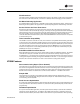
Troubleshooting Figure 57. Sensor signal vs. airflow delivery 5 Flow Sensor DP (In . w g ) 1 4" 5" 6" 8" 1 0 " 1 2 " 1 4 "1 6 " 0.1 0.01 10 100 1,000 10,000 C fm • Check the tubing for reversal and/or leaks. • Check the flow ring for plugged holes. Blow out with compressed air if necessary. 3. Wrong unit size downloaded into the VAV VV550 Controller setup menu • Verify that the actual unit size matches the unit's nameplate. 4.
Troubleshooting Duct Temperature Sensor Failure Procedures In the event that the VV550 reports an incorrect or failed Discharge or Primary air temperature, properly inspect the following: 1. Make sure VAV VV550 has been configured for the input 2. Discharge or Primary air temperature is higher or lower than what the VV550 reads • Check the location and installation of the sensor. Change the calibration factor in the VV550 setup screens. Note: If sensor is off more than ± 2 degrees continue to number 3. 3.
Troubleshooting • Change the heat and/or cool set points. 3. Actuator not driving full drive time • Drive time in advanced configuration not set at 90 seconds on current Varitrane units • Adjust to correct damper travel time using Rover service tool. See Operation and programming chapter. • Damper actuator loose on shaft • Tighten damper actuator set screw to damper shaft • Measure the power input to TB1-1 24VAC input and TB1-2 on the VAV VV550 Controller board.
Troubleshooting 3. Tracer Summit has the fan output disabled • Check group, global, and/or Tracer overrides to make sure they are not inhibiting fan operation. 4. A flow override exists locking out the fan output • Check to make sure Tracer or Rover service tool has released fan disable override. 5. If the VAV VV550 Controller is calling in the status menu for the Fan to be on and it is not then check VV550 Triac output wiring; and Relay output.
Troubleshooting • Check group, global, and/or Tracer overrides to make sure they are not inhibiting fan operation. 4. A flow override exists locking out the fan output • Check to make sure Tracer or Rover has released fan disable override. Note: If fan cycling is based on temperature go to step 5 and if it is based on air flow go to step 6. 5. If fan control is based on temperature and Zone temperature is at or above the heating set point plus heating offset on units configured as temperature control.
Troubleshooting • Check wiring to make sure speed control is wired correctly. See Figure 63, p. 111 to Figure 64, p. 112 for wiring schematic. • Check voltage selection switch on side of Variable speed motor control. • Should be set for motor voltage.
Troubleshooting • Measure voltage from green to red wires on 4 pin connector and document. See Figure 59, p. 107 to Figure 66, p. 114 for correct unit wiring diagram. • Should measure less than previous reading • Continue process until all selector switch positions have been checked to find any dead spots in selector switches • If unit ECM board fails any of these tests replace board. If ECM is found to be good but motor still does note operate, change out motor. Figure 58.
Troubleshooting • Check power output for correct binary output. Should have 24VAC; if it does not measure the power input to on TB1-1 24VAC input and TB1-2 of the VV550 board. The supply voltage should be between 20 and 28 VAC (24VAC cataloged). However, voltages at either extreme may result in system instability. • Heat Triac(s) can be checked with purchasing a 24VAC light bulb and see if it lights up on call for Heat stage VV550. If light bulb does not light up replace VV550.
Troubleshooting Notice: Equipment Damage! VAV VV550 Controller outputs are switched to ground. Do not jumper 24VAC to Binary output Triacs because damage will occur. Trane/Honeywell Proportional Valve Check Out Procedures Two problems can occur with the cartridge/ actuator or both that can result in over conditioning the space.
Troubleshooting • If VAV VV550 is calling in the status menu and binary output to open the valve and Triac is not energized then check VV550 Triac output; wiring; and Relay output. • Check Binary outputs. See Figure 59, p. 107 and Figure 60, p. 108 for correct outputs. Should have 24VAC; if it does not measure the power input to TB1-1 24VAC input and TB1-2 of the VV550 board. The supply voltage should be between 20 and 28 VAC (24VAC cataloged).
Troubleshooting Figure 59.
Troubleshooting Figure 60.
Troubleshooting Figure 61.
Troubleshooting Figure 62.
Troubleshooting Figure 63.
Troubleshooting Figure 64.
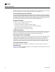
Troubleshooting Figure 65. ECM fan-powered with single phase voltage electric heat FAN-POWERED UNITS - VV550 - ECM MOTOR HEATER TERMINALS - TYPICAL OF SINGLE PHASE VOLTAGES 1. L1 L2 N - 208, 240, 480 L1 N - 277, 347 L1 L2 N LINE VOLTAGE (SEE NAMEPLATE) CONTACTOR MANUAL CUTOUT 1ST STAGE CONTACTOR 2ND STAGE SINGLE PHASE LINE VOLTAGES STAGES 1 2 L1 L2 N OPTIONAL FUSE OPTIONAL FUSE G 1.
Troubleshooting Figure 66.
Literature Order Number www.trane.com For more information, contact your local Trane office or e-mail us at comfort@trane.com VAV-SVP01A-EN Date May 2010 Supersedes VAV-SVP01A-EN February 2010 Trane has a policy of continuous product and product data improvement and reserves the right to change design and specifications without notice.