
Programming Guide

90 VAV-SVP01A-EN
Troubleshooting
Wired Zone Setpoint Failure Procedures
WARNING
Hazardous Service Procedures!
The maintenance and troubleshooting procedures recommended in this section of the manual
could result in exposure to electrical, mechanical or other potential safety hazards. When
possible, disconnect all electrical power including remote disconnect and discharge all energy
storing devices such as capacitors before servicing. Follow proper lockout/tagout procedures to
ensure the power can not be inadvertently energized. When necessary to work with live
electrical components, have a qualified licensed electrician or other individual who has been
trained in handling live electrical components perform these tasks. Failure to follow all of the
recommended safety warnings provided, could result in death or serious injury.
In the event that the VV550 reports an incorrect zone setpoint, properly inspect the following:
1. Zone sensor setpoint wired incorrectly
• Check wiring for the correct connections.
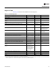
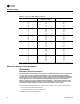
2. Defective zone sensor setpoint dial
Table 19. Zone sensor temperature resistance
Temp (
o
F) Thermostat Thumbwheel
Resistance (Ohms)
Sensor Resistance (k Ohms)
55
56
57
58
59
792
772
753
733
714
17.0
16.5
16.1
15.7
15.4
60
61
62
63
64
694
675
656
636
617
15.0
14.6
14.3
14.0
13.6
65
66
67
68
69
597
578
558
539
519
13.3
13.0
12.6
12.3
12.1
70
71
72
73
74
500
481
461
442
422
11.8
11.5
11.2
11.0
10.7
75
76
77
78
79
403
383
364
344
325
10.4
10.2
10.0
9.7
9.5
80
81
82
83
84
85
306
286
267
247
228
208
9.3
9.0
8.8
8.6
8.4
8.2
Note: Thumbwheel resistance checks are made at terminal 2 and 3 on the zone sensor. Temperature sensor resistance is
measured at terminal 1 and 2 of the zone sensor.