WSHP-IOP-2 May 1998 Installation, Operation, and Programming Tracer™ ZN510 Controller
Literature History The Trane Company has a policy of continuous product improvement and it reserves the right to change specifications and design without notice. Installation, Operation, WSHP-IOP-2 and Programming Library Service Literature Product Section Unitary Product Water-Source Heat Pumps Model 000 Literature Type Installation, Operation, and Programming Sequence 1 Date April 1998 File No.
Table of Contents Start-up Procedure Power-up Sequence Unit Identification Tag Unit Operation General Information Communication Power Binary Outputs Analog Outputs Binary Inputs Analog Inputs Zone Sensors Heating or Cooling Control Mode Operation Single or Dual Compressor Operation Data Sharing Configuration Troubleshooting Diagnostics ZN510 Controller Replacement Wiring Diagram Hardware Specifications Appendix 4 5 6 7 7 7 8 8 9 9 12 15 18 19 20 21 22 27 28 29 31 33
Start-up Procedure Installation of New Units 1. Follow all instruction for installation of water source heat pumps as detailed in the IOM (Installation Operation Maintenance manual). 5. Verify that water connections have been made to unit, then ensure that water is circulating through the unit. 6. Reapply power. 2. Disconnect power or disable the circuit breaker to unit. 7. Check for STATUS GREEN LED operation to ensure power and communication has been made 3.
Power Up Sequence Power Up Sequence When 24 VAC power initially is applied to the ZN510 controller, the following sequence occurs: 1. All outputs are controlled off. 2. The controller reads all inputs to determine their initial values. 3. A random start time is hard coded on every board and cannot be disabled. The board generates a random time delay between 0 and 25 seconds. Once this time expires, the power up control wait time (if configured) will wait for 120 seconds.
Unit Identification Tag Unit Identification Tag The unit identification tag is factory mounted and provided for easy identification of an installed unit. It contains model number, tagging, and location information. See Figure 1. The top portion of the unit identification tag remains permanently affixed to the unit for identity purposes. The bottom portion of the tag provides pertinent information that is removable to be placed on building plans or in the ZN510 IOP on page 33.
Unit Operation General Information The ZN510 controller is a microprocessor-based direct digital controller that controls a variety of water source heat pump equipment including: z Standard efficiency horizontal and vertical units up to 10 tons. z High efficiency horizontal and vertical units. z Console water source heat z Up to two compressors. pumps. z Reversing valve. ZN510 is designed to provide accurate and reliable zone temperature control by using custom proportional integral (PI) algorithms.
Unit Operation Power The ZN510 controller is powered by 24 VAC. A total of two 1/4-inch quickconnect terminals are provided for 24 VAC connection to the board. See Figure 4 for ZN510 power requirement. Factory Supplied Transformer Line Voltage 24VAC Note: Power for field installed ancillary devices is not available from the board. It must be tapped at transformer. See Table 21 for excess power available. Note: z During occupied mode, the outdoor air damper is closed when the fan is controlled off.
Unit Operation z Verify output wiring and operation without using Trane’s service tool, Rover. Analog Outputs Binary Inputs The ZN510 controller has three available binary inputs (BI). These inputs are factory-configured for the following functions: z Force compressor operation, allowing the technician to use refrigerant gauges or other test equipment to verify unit operation. manual output test. See Troubleshooting section for Green LED and Testing Heat Pump Configurations on page 21 & 22.
Unit Operation Low Temperature Detection The low temperature detection diagnostic protects the heat exchanger by using an analog leaving water temperature sensor to protect refrigerant circuit 1 and a binary low temperature detection device to protect refrigerant circuit 2. Each individual refrigerant circuit is disabled when the low temperature condition exists for that circuit. outdoor air damper also operates normally.
Unit Operation In Occupied mode, the controller operates according to the occupied setpoints. In Occupied Standby Mode, the unit controller operates according to the Occupied Standby setpoints. When the controller receives a communicated unoccupied request, the controller operates according to the unoccupied setpoints regardless of the state of the hardwired occupancy input.
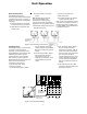
Unit Operation 24 VAC Compr 2 HPC Compr 1 LPC Binary Outputs Figure 7: High and low pressure switch Note: The ZN510 controller includes an automatic diagnostic reset function that allows the controller to automatically recover after a high or low pressure cutout diagnostic. After 30 minutes the controller will reset the diagnostics. Most diagnostics occur due to intermittent water temperature or flow problem. The “smart reset” may eliminate many service calls.
Unit Operation Space Temperature ZN510 controls the space temperature according to the active space temperature, the active heating/cooling setpoint, and the space temperature control algorithm. The ZN510 controller receives the space temperature from either a wired zone sensor or as a communicated value. When neither a zone sensor nor communicated space temperature is present, the ZN510 controller generates a space temperature failure diagnostic.
Unit Operation Possible Fan Modes Heat Pump (1-speed) OFF Fan Off Continuous: (Field Modified) AUTO z In occupied mode, the fan runs continuously. In unoccupied mode, the fan cycles OFF when no heating or cooling is required. Cycling: (Factory Default) AUTO z The fan cycles ON and OFF with compressor operation. The ZN510 controller receives the fan mode from either a wired zone sensor or as a communicated valve.
Zone Sensor Zone Sensor The ZN510 controller accepts the following zone sensor inputs: values exist, the controller ignores the hardwired space temperature input and uses the communicated value. z Space temperature mea- surement. z Local setpoint (internal or external on the zone sensor). z Fan switch. (Optional) z Timed override (ON and CANCEL). z Communication Jack.
Zone Sensor Zone Sensor Features Fan Switch (Optional) The zone sensor fan switch provides the controller with an occupied (and occupied standby) fan request signal of OFF or AUTO. If the fan control request is communicated to the controller, the controller ignores the hardwired fan switch input and uses the communicated value. The zone sensor fan switch signal can be enabled or disabled through configuration in the ZN510 controller.
Zone Sensor Specifications Part Number: X13510606020 Description: z Space temperature (0.2 C resolution). z External setpoint. z ON and CANCEL buttons. z Communication jack. z Vertical case with Trane logo. Part Number: X13510635010 Description: z Space temperature (0.2 C resolution). z External setpoint. z Fan Switch (OFF and AUTO). z ON and CANCEL buttons. z Communication jack. z Vertical case with Trane logo.
Heating or Cooling Control Mode Operation Heating or Cooling Operation For both single and dual compressor operation, the ZN510 controller cycles the compressor(s) on and off to meet heating or cooling zone demands. The controller uses the unit capacity and pulse width modulation (PWM) logic along with minimum on/off timers to determine the operation for compressor 1.
Single and Dual Compressor Operation Other Modes Occupancy Operation Unoccupied operation normally is associated with evening hours when the space is vacant. In unoccupied mode, the controller always uses the default unoccupied heating and cooling setpoints stored in the controller. As the unit goes unoccupied, the compressors ON timers are ignored and the compressors are disabled.
Data Sharing Master Controller ZN510 can send or receive data (such as setpoint, heat/cool mode, fan request and space temperature) to and from other controllers on the communication link, with or without a building automation system. This includes applications where multiple unit controllers share a common space temperature sensor, both for standalone and building automation applications.
Configuration Configurable Parameters Rover, Trane’s service tool, uses the unit type “heat pump” to determine and download unit configuration information, such as the default analog inputs, the default binary inputs, and the default binary output configurations. See Table 7 for default configurations for heat pumps. Table 8: Heat pump heating or cooling operation.
Troubleshooting Red Service LED Table 9: Red LED activity Red LED Activity Description LED off continuously when power is applied to the controller. Normal operation. LED on continuously, even when power is applied to the controller. Someone is pressing the service button or the controller has failed. LED flashes once every second. Use Rover, Trane’s service tool, to restore the unit to normal operation or unconfigured.
Troubleshooting Manual Output Testing the Heat Pump Configurations The procedure for testing heat pump configurations is: 1. Press and hold the Test button 3. for at least three seconds to start the test mode. 2. The test sequence resets diagnostics and turns off all outputs. Press the Test button several more times (no more than once per second) to advance through the test sequence. Table 12: Test sequence Step Fan BOP 1 Reversing Valve BOP 2 Compr 1 BOP 4 Compr 2 BOP 5 Damper BOP 6 1.
Troubleshooting Questionable Unit Operation Table 13: Fan output does not energize Probable Cause Random start observed. Explanation After power up, the controller always observes a random start from 0 to 25 seconds. The controller remains off until the random start time expires. When power up control wait is enabled (non-zero time), the controller remains off until one of two conditions occurs: Power up control wait.
Troubleshooting Questionable Unit Operation Table 14: Compressor(s) not running Probable Cause Explanation Normal operation. The controller compressor(s) turn on and off to meet the unit capacity requirements. Requested mode off. The desired operating mode (such as off, heat and cool) can be communicated to the controller. When off is communicated to the controller, the unit shuts off all unit compressor(s). Communicated disable.
Troubleshooting Questionable Unit Operation Table 16: Outdoor air damper stays closed Probable Cause Explanation Normal operation. The controller opens and closes the outdoor air damper based on the controller’s occupancy mode and fan status. Normally, the outdoor air damper is open during occupied mode when the fan is running and closed during unoccupied mode. Refer to the outdoor air damper section on page 8. Warm up and cool down.
Diagnostics Table 17: ZN510 controller diagnostics Diagnostic Fan Other Outputs Condensate overflow Off Compressors: Off Damper: Closed Low temp detect - Crt 1 Enabled Compressor 1: Off Compressor 2: See note below. Damper: See note below. Low temp detect - Crt 1 Enabled Compressor 1: See note below. Compressor 2: Off Damper: See note below.
Diagnostics Translating Multiple Diagnostics The controller senses and records each diagnostic independently of the diagnostics. It is possible to have multiple diagnostics present simultaneously. The diagnostics are reported in the order they occur. Resetting Diagnostics 1. Automatically by the controller. 2. 3. 4. By initiating a manual output test at the controller. By cycling power to the controller. Through a building automation system such as ZN510 Loop Controller. 5.
Wiring Diagram 29
Wiring Diagram 30
Hardware Specifications Specifications Board Dimensions Height: 4” (102 mm) Width: 5-1/2” (140 mm) Depth: 2-1/4” (57mm) Operating Environment 32 to 140 F (0 to 60 C) 5 to 95% non-condensing Storage Environment -40 to 185 F (-40 to 85 C) 5 to 95% non-condensing Power Requirements 18 to 32 VAC (24 VAC nominal) 50 or 60 Hz 300 mA Agency Listings UL and CUL 916 Energy Management System Agency Compliance IEC 1000-4-2 (ESD), IEC 1000-4-4 (EFT), IEC 1000-4-5 (Surge), FCC Part 15, Class A.
Hardware Specifications Table 18: Binary Inputs Description Terminals Function Binary Input 1 J2-1 J2-2 Input Binary Input 2 J2-3 24 VAC J2-4 Input J2-5 24 VAC J2-6 Input Binary Input 3 24 VAC Table 19: Binary Outputs Description Terminals Output Rating Load Energized Load De-energized Binary Output 1 J1-1 12 VA 1 VAC RMS (typical) 24 VAC RMS (typical) Binary Output 2 J1-2 12 VA 1 VAC RMS (typical) 24 VAC RMS (typical) Binary Output 3 J1-4 NOT USED Binary Output 4 J1-5