Installation Operation Maintenance Voyager™ I Rooftop Units Cooling-only TSD/TSH 060 072 102 120 Reversible WSD/WSH 060 072 090 Gas-fired YSD/YSH 060 072 090 102 120 RT-SVX20A-E4
General information Foreword Warnings and cautions These instructions are given as a guide to good practice in the installation, start-up, operation, and maintenance by the user, of Trane TSD/TSH, WSKD/WSH and YSD/YSH units. They do not contain full service procedures necessary for the continued successful operation of this equipment. The services of a qualified technician should be employed through the medium of a maintenance contract with a reputable service company.
General information Reception Refrigerant Maintenance contract On arrival, inspect the unit before signing the delivery note. In case of visible damage: The consignee (or the site representative) must specify any damage on the delivery note, legibly sign and date the delivery note, and the truck driver must countersign it. The consignee (or the site representative) must notify Trane Epinal Operations - Claims team and send a copy of the delivery note.
Contents General information 2 Foreword Warnings and Cautions Reception Warranty Refrigerant Maintenance contract Storage Training 2 2 3 3 3 3 3 3 Installation 6 Reception of units Roof curb installation Dimensions/Weights/Clearances Installing the unit Connection of duct network Condensate drain piping Gas pipework installation Filter installation Supply fan adjustment Component air pressure drops Supply fan performances Electrical connection 6 6 7 9 10 12 13 14 14 16 17 30 Controls 33 Control wi
Contents Unit Options 44 Hot water coil Electric Heater Soft Starter 0 - 25% fresh air hood Barometric relief Operation 44 45 45 46 47 48 Operation with a conventional thermostat Setting the economizer Test procedures Test modes Unit Start-up Cooling without an Economizer Low Ambient Operation Cooling with an Economizer Economizer Set-Up ReliaTel™ Control Heating Operation Ignition Module Final installation checklist Maintenance 48 50 52 53 54 56 57 57 58 58 58 59 60 End user routine maintenance S
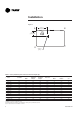
Installation General information: The installation must conform to all local standards and regulations. Reception of units Rooftop unit There are two ways to handle the unit: 1. Use the openings in the base to handle the machine using a forklift, in accordance with applicable safety regulations. 2. Use a lifting beam correctly adjusted to fit the unit (Figure 1). Unit handling The units are supplied on the truck but are not unloaded.
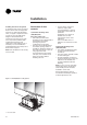
Installation Dimensions/Weights/ Clearances Figure 3 - Minimum clearances The structure accommodating the unit(s) must be designed to support the equipment in operation, as a minimum. Refer to Table 2 and the space requirement plan.
Installation Figure 4 A Center of gravity length B Center of gravity width C D Center of gravity Table 3 - Factory-installed options and accessories net weights (kg) Motorized Outside Air Damper Manual Outside Air Damper Economizer Barometric Relief TSD/TSH 060 11,8 3,2 9,1 7,3 31,8 TSD/TSH 072 16,3 4,5 13,6 11,8 52,2 TSD/TSH 090 16,3 4,5 13,6 11,8 52,2 3,6 13,6 17,0 TSD/TSH 1020 16,3 4,5 13,6 11,8 52,2 3,6 13,6 19,0 TSD/TSH 120 16,3 4,5 13,6 11,8 52,2 3,6 13,
Installation Installing the unit Discharge Conversion If a unit is to be converted to Vertical discharge, a panel must be acquired from Trane. If a unit is to be converted to Horizontal discharge, the following conversion must be performed: 1. Remove the return and supply duct covers. 2. Apply gasket to the return duct cover. 3. Position duct covers as shown in Figure 4.
Installation Installing the unit on the ground To install the unit on the ground, its base must be level and supported securely. For horizontal discharge units, a support is required such as a metal or concrete slab whose height must be determined according to the amount of snow cover, to prevent problems with condensation drainage and obstruction of the external coil. If necessary use an anti-vibration material between the rooftop unit's base and the support.
Installation Table 4 - Duct dimensions for downflow units (mm) Unit size A B C D E Flanges TSD 060 619 357 411 459 356 32 YSD 060 610 356 394 457 356 32 WSD 060 819 357 411 459 356 32 TSD/WSD 072/090 875 451 451 875 356 31 TSD 102/120 875 451 451 875 356 31 YSD 072/090/102/120 816 444 444 838 356 31 Table 5 - Duct dimensions for downflow units (mm) Unit size A B C D TSH/WSH 060 591 337 375 438 YSH 060 591 337 375 438 TSH/WSH/YSH 072/090 832 4
Installation Condensate drain piping Figure 10 - Condensate drain location A 3/4" condensate drain connection with P-trap is provided. Follow local codes and standard piping practices when running the drain line. Install a trap and be sure to fill with water before starting the unit. Pitch the line downward, away from the unit to avoid long, level, horizontal runs. Refer to Figure 11. The condensate drain is reversible to allow installation of a drain tap on either side of the unit.
Installation The installation must conform to all standards and regulations. CAUTION! Should the pressure at the unit valve gas inlet be higher than 0.035 bar, an expansion valve must be installed. The gas supply pipework and gas stop valve to be installed near the unit must be sized so as to ensure the gas pressure is sufficient at the unit inlet when operating at full load. The pipework must be selfsupporting and the final connection to the burner must be made by a flexible pipe.
Installation Filter installation Supply fan adjustment To gain access to filters, remove the supply fan access panel on downflow units and the filter access panel on the end for horizontal units. Use the following procedure to determine the proper adjustment of the supply fan for a specific application. 1. Determine total external static pressure about system and accessories. • Obtain the design airflow rate and the design external static pressure drop through the distribution system.
Installation To increase airflow To adjust belt Loosen variable sheave set screw and turn sheave clockwise. The fan belts must be inspected periodically to assure proper unit operation. Replacement is necessary if the belts appear frayed or worn. To decrease airflow Loosen variable sheave set screw and turn sheave counter-clockwise. Units with dual belts require a matched set of belts to ensure equal belt length. When removing or installing the new belts, do not stretch them over the sheaves.
Installation Component air pressure drops Table 9 - Pressure drop through accessories Unit size 060 072 090 102 120 16 Filter EU4/G4 Economizer 100% outside air Airflow (m3/h) Filter EU2/G2 Electric heater Hot water coil 3060 31 50 38 17 49 3400 38 55 46 21 55 3740 46 61 55 25 62 4080 55 66 64 30 68 3670 13 37 27 7 46 4080 16 42 29 9 52 4490 19 46 31 11 58 4900 23 50 33 13 64 66 4590 19 47 33 12 5100 24 52 39 15 74 5610 29 57 45 20
Installation Supply fan performances Table 10 - TSD 060 Available static pressure External Static Pressure (Pa) 25 50 75 100 125 150 175 200 225 250 275 300 m3/h RPM kW RPM kW RPM kW RPM kW RPM kW RPM kW RPM kW RPM kW RPM kW RPM kW Fan RPM kW Fan RPM kW 2720 - - - - - - - - - - 899 0.43 944 0.49 985 0.54 1023 0.59 1060 0.64 1093 0.69 1126 0.74 3060 - - - - - - - - 904 0.49 947 0.54 988 0.58 1028 0.64 1067 0.70 1104 0.
Installation Table 12 - TSD 072 Available static pressure External Static Pressure (Pa) 25 50 75 100 125 150 175 200 225 m3/h RPM kW RPM kW RPM kW RPM kW 3260 - - - - - - - - - - 726 0.41 769 0.47 811 0.52 851 3670 - - - - - - - - 706 0.43 751 0.49 792 0.55 832 0.61 871 4080 - - - - - - - - 732 0.51 777 0.58 818 0.64 856 0.71 893 4490 - - - - - - 715 0.54 758 0.60 802 0.68 845 0.75 883 0.
Installation Table 14 - TSD 090 Available static pressure External Static Pressure (Pa) 25 50 75 100 125 150 175 200 225 m3/h RPM kW RPM kW RPM kW RPM kW RPM kW RPM kW 4080 - - - - - - - - 750 0.54 794 0.60 834 0.67 873 0.73 909 4590 - - - - - - - - 787 0.66 830 0.74 871 0.82 908 0.89 943 5100 - - - - 747 0.68 789 0.74 827 0.82 867 0.90 906 0.98 944 1.06 980 RPM kW RPM kW RPM 250 kW 275 Fan RPM kW 0.87 980 1.
Installation Table 16 - TSD 102 Available static pressure External Static Pressure (Pa) 25 50 75 100 125 m3/h RPM kW RPM kW RPM kW RPM kW 4620 - - - - - - - - 5200 - - - - - - - - 5780 - - - - - - 689 0.68 RPM 150 175 200 225 250 275 RPM kW RPM kW RPM kW Fan RPM 0.71 769 0.81 802 0.90 833 1.00 0.83 796 0.93 828 1.03 861 1.13 0.96 825 1.07 856 1.18 887 kW RPM kW RPM kW - - 695 0.62 733 688 0.64 725 0.73 761 724 0.
Installation Table 18 - TSD 120 Available static pressure External Static Pressure (Pa) 25 50 75 100 125 150 m3/h RPM kW RPM kW RPM kW RPM kW RPM kW 5440 - - - - - - - - - - 6120 - - - - - - - - - - RPM 175 200 225 kW RPM kW RPM kW RPM - - 789 0.93 822 1.03 797 0.99 829 1.10 860 1.22 250 275 Fan RPM kW 300 Fan RPM kW RPM kW kW 856 1.14 887 1.25 917 1.36 945 1.47 892 1.34 922 1.46 951 1.57 979 1.
Installation Table 20 - YSD 060 Available static pressure External Static Pressure (Pa) 25 50 75 100 125 150 175 m3/h RPM kW RPM kW RPM kW RPM kW RPM kW RPM kW 2720 - - - - - - - - - - - - 3060 - - - - - - - - - - - - 3400 - - - - - - - - 1052 0.73 1089 0.79 3740 - - - - 1051 0.82 1087 0.87 1122 0.92 1156 4080 1055 0.90 1093 0.97 1127 1.03 1160 1.09 1193 1.
Installation Table 22 - YSD 072 Available static pressure External Static Pressure (Pa) 25 50 75 100 125 150 225 250 275 300 RPM kW RPM kW RPM kW RPM kW Fan RPM kW Fan RPM kW - - 820 0.54 859 0.60 896 0.66 932 0.72 968 0.78 1000 0.84 814 0.58 854 0.64 891 0.71 928 0.78 963 0.84 996 0.91 1028 0.98 853 0.70 890 0.77 926 0.84 961 0.91 994 0.98 1027 1.05 1058 1.13 0.77 894 0.84 929 0.91 963 0.98 996 1.06 1028 1.14 1060 1.22 1090 1.
Installation Table 24 - YSD 090 Available static pressure External Static Pressure (Pa) 25 50 75 100 125 150 175 m3/h RPM kW RPM kW RPM kW RPM kW 4080 - - - - - - - - - - 869 0.73 906 4590 - - - - - - - - 887 0.85 922 0.92 958 RPM kW RPM kW RPM 200 kW 225 RPM kW 0.80 941 0.99 991 250 275 RPM kW RPM kW 0.87 976 0.94 1009 1.01 1.07 1024 1.14 1055 1.22 Fan RPM 300 kW Fan RPM 1042 1.09 1073 1.17 1086 1.30 1117 1.39 1.
Installation Table 26 - YSD 102 Available static pressure External Static Pressure (Pa) 25 50 75 100 125 150 m3/h RPM kW RPM kW RPM kW RPM kW RPM kW 4620 - - - - - - - - - - 5200 - - - - - - - - - - 5780 - - - - - - - - 805 1.00 6350 - - - - 792 1.00 823 1.10 854 1.21 6930 786 1.03 818 1.14 848 1.24 877 1.34 905 1.
Installation Table 28 - YSD 120 Available static pressure External Static Pressure (Pa) 25 50 75 100 125 150 175 200 m3/h RPM kW RPM kW RPM kW RPM kW RPM kW RPM kW 5440 - - - - - - - - - - - - 6120 - - - - - - - - - - - - 6800 - - - - - - - - 913 1.48 941 1.60 969 1.73 7480 - - 895 1.48 923 1.59 949 1.70 976 1.83 1003 1.96 1029 2.10 8160 939 1.75 967 1.87 992 1.99 1017 2.12 1042 2.24 1066 2.38 1090 2.
Installation Table 30 - WSD 060 Available static pressure External Static Pressure (Pa) 25 50 75 100 125 150 m3/h RPM kW RPM kW RPM kW RPM kW 2720 - - - - - - - - - - 3060 - - - - - - - - 892 0.48 3400 - - - - - - 904 0.55 945 0.60 3740 - - - - 913 0.63 959 0.68 1001 4080 - - 933 0.74 972 0.78 1014 0.84 1056 325 m3/h Fan RPM 350 kW Fan RPM RPM kW RPM 175 200 225 250 275 300 RPM kW RPM kW Fan RPM kW 0.53 1014 0.
Installation Table 32 - WSD 072 Available static pressure External Static Pressure (Pa) 25 50 75 100 125 150 175 200 225 250 kW Fan RPM kW 0.62 912 0.68 948 0.75 982 0.81 0.72 936 0.79 971 0.86 1004 0.93 0.83 961 0.91 995 0.98 1027 1.06 0.97 987 1.04 1021 1.12 1053 1.20 1018 1.20 1050 1.28 1081 1.36 RPM kW RPM kW RPM kW RPM kW RPM kW RPM kW RPM kW RPM kW 3260 - - - - - - - - 705 0.38 751 0.44 794 0.
Installation Table 34 - WSD 090 Available static pressure External Static Pressure (Pa) 25 50 75 100 125 150 175 200 225 m3/h RPM kW RPM kW RPM kW 4080 - - - - - - - - 768 0.56 810 0.63 850 0.70 888 4590 - - - - - - 763 0.63 807 0.70 850 0.78 889 0.85 926 5100 - - - - 770 0.71 810 0.78 849 0.86 890 0.95 929 1.03 967 5610 - - 782 0.83 823 0.90 861 0.97 897 1.05 933 1.12 969 1.23 1006 6120 798 0.94 838 1.04 876 1.12 913 1.
Installation Electrical connection Over current protection The electric panel is located in the unit compressor section. Remove the compressor access panel. The unit is designed to run with 400 V +/- 5%/50 Hz/ 3 ph. The branch circuit feeding the unit must be protected in accordance with national or local codes and maximum unit amps indicated in Table 36. Factory supplied disconnect switch (option) Power wiring The disconnect switch is factory mounted. It is located in the compressor section.
Installation The "ABC" indicator on the face of the phase indicator will glow if phase is ABC for terminals L1, L2, L3. WARNING! Disconnect all power, including remote disconnects, and discharge all capacitors before servicing. IMPORTANT! After completion of wiring, check all electrical connections, and ensure all connections are tight. Replace and secure all electrical box covers and access doors before leaving unit or connecting power to circuit supplying the unit.
Installation Table 37 - Compressor and condenser motors Compressor motor Condensor fan motor Number of motors Main power supply (V) Number of phases Motor HP (kW) TSD/TSH 060 1 400 3 4,2 10,3 74 1 400 1 TSD/TSH 072 1 400 3 5,6 13,7 95 1 400 1 TSD/TSH 090 1 400 3 6,2 14,3 100 1 400 1 TSD/TSH 102 2 400 3 4.5 / 2.8 10 / 7.5 74 / 48 2 400 TSD/TSH 120 2 400 3 4.5 / 3.5 10.7 / 9.
Controls Control wiring The control circuit is 24 V AC. Unit includes a 400/24 V transformer. WARNING! The unit disconnect switch must be opened and locked open. Risk of injury and electrocution. CAUTION! The unit 24 V transformer must not be used to power accessories mounted on site, other than those proposed by Trane.
Controls Trane THS01,THS02, THP01 and THP02 Thermostats are directly connected to RTRM board (J7 connector). Trane THS03 and THP03 thermostats are directly connected to RTRM board (J6 connector). Install the electrical link between the thermostat (thermostat terminal strip) and the unit (J6 or J7 connector) in compliance with the interconnection diagram. The low voltage wiring must not be laid in the same pipes as the power cables.
Controls CO2 sensors Wall-mounted and duct-mounted CO2 sensors The CO2 sensor is designed to operate with a nominal 24 Vac supply. The power supply should maintain the voltage between 20 to 26 Vac. Power supply requirements CAUTION! Make sure that you connect the power wire only to the 24V terminal. Connecting the power wire to the output terminal may result in equipment damage.
Controls Wiring the wall-mounted CO2 sensor DVC setpoint potentiometer on economizer module can be adjusted as follows: 0% - 500ppm, 50% - 1000 ppm, 100% - 1500ppm The outside air damper will modulate from minimum position setting to up to 100% while attempting to maintain the CO2 setpoint. Wiring the duct-mounted CO2 sensor 1. Connect the common wire from the controller to the ground terminal (terminal 0) (Figure 16). 2. For voltage output, connect the signal wire to terminal V. 3.
Controls Mounting the wall-mounted sensor 1. Select a proper location in the room to mount the CO2 sensor. Look for an interior wall with good air circulation, approximately 1.4 m from the floor. 2. Remove the back plate from the sensor and thread the power wires and output signal wire through the hole in the back plate (Figure 17). For surface wiring, make cutouts with pliers to the thinner section of the upper or lower edge of the back plate and to thread the wires through. 3.
Controls Mounting the duct-mounted CO2 sensor 1. Select a proper location on the duct to mount the CO2 sensor. 2. Drill a 22-25 mm hole in the mounting surface for sensor insertion (Figure 19). 3. Attach the mounting plate to the duct wall with four screws. 4. Insert the sensor through the mounting plate, adjusting the depth for optimal air sensing. Figure 19 - Duct-mounted CO2 sensor diameter 15/8 in. (42 mm) 7 /8 in.
Controls Remote potentiometer To install the remote potentiometer, cut the jumper WL on the economizer ECA board, and connect the wires to J11 and J12. Note: This potentiometer allows to adjust the permanent fresh air intake from 0 to 50%. 0 W corresponds to closed fresh air damper. 270 W corresponds to 50% open fresh air damper.
Controls Fire thermostat There are two sensors in the fire thermostat Kit: Sensor X1310004001 is factory-set to open at 57°C, Sensor X13100040-02 is set to open at 115°C. Sensors are mounted directly in the ductwork. They should be installed where elements can respond quickly to air temperature changes. If not possible, the sensor may be installed on a suitable bracket so the air is drawn across the element. Sensor X13100040-01 has to be mounted in the return air duct.
Controls Clogged filter detector Smoke detector This device is mounted in the indoor fan section. The sensor measures the difference in pressure before and after the filter section. The information is sent to the THP03 thermostat, to a Tracker™ or to a BMS. The setting range is 40 to 300 Pa. This device is used to detect smoke in the air stream. It includes a factory mounted detector connected to a central panel, both fitted in the fan section. When smoke is detected, it shuts off the unit.
Controls "THS" are non programmable thermostats, "THP" are programmable. Thermostats 6 thermostats are available: THS01/THP01, THS02/THP02 and THS03/THP03. 01 and 02 series are conventional thermostat, 03 series are dedicated to the controller. Table 42 - Thermostat features THS01 THP01 THS02 THP02 THS03 THP03 non-programmable X - X - X - programmable - X - X - X electronic X X X X X X Reliatel Reliatel unit control type design electromech. electromech. electromech.
Controls Other accessories available Remote temperature sensor to be used with THS/THP 01-02. TZS01: Remote room temperature sensor to be used with THS/THP 03, Tracker or Varitrac systems. DTS: Duct temperature sensor to be used with THS/THP 03. TZS02: Remote room temperature sensor with adjustable thumwheel setpoint to be used with Tracker or Varitrac systems. TZS04: Room temperature sensor with adjustable thumbwheel and override button, to be used with Tracker or Varitrac systems.
Unit Options Hot water coil (Down flow units only) In order to prevent water to freeze up in the coil during unoccupied period or shutdown limited period, a thermostat opens when there is a risk of freeze-up. The services of a water treatment specialist are recommended if water used can cause scaling deposits or erosion. Insulate all the water piping likely to be exposed to freezing temperatures in order to avoid freeze up of the coil and heat losses.
Unit Options Electric Heater Soft Starter Electric heaters are fitted on the fan discharge. The soft starter is used to achieve a progressive supply fan start and a reduced starting current as well as the motor starting torque. This option is well adapted for textile duct applications. It is factory installed in the main control panel.
Unit Options This option includes for the hood itself, a wire mesh and a slidable damper. 0 - 25% fresh air hood The 0-25% fresh air hood allows to introduce fresh air into the unit. The slidable damper has to be adjusted manually by removing the screws and sliding it off up or down (Figure 28). This is a manual device fitted on the back of the unit, sized for a maximum of 25% of the nominal rooftop air flow. The amount of fresh air introduced is then permanently fixed.
Unit Options Barometric relief This option includes exhaust hoods and gravity dampers located in the return air section. When the pressure of the building increase, the gravity dampers open and relieve air to the outside. The barometric relief allows to minimize overpressure in the building caused by the introduction of fresh air. This option is typically installed when fresh air intake is below 25% of the nominal air flow and when the return air pressure drop is below 25Pa.
Operation Operation with a conventional thermostat The ReliaTel module has conventional thermostat connections as well as Zone Sensor Module connections. When a conventional thermostat is controlling the unit, operation differs as follows: • Supply Air Tempering feature is not available. If outdoor air is being introduced through the equipment, discharge air temperature may be cold when not actively heating. • Proportional Integral (PI) control is not available.
Operation Conventional thermostat signals represent direct calls for unit functions. In their simplest applications, thermostat contacts directly control contactors or other load switching devices. This function provides inputs for the thermostat signals and processing to enhance reliability and performance. Compressor protection and reliability enhancement functions (HPC, LPC, Minimum On/Off timers, etc.). All operate the same whether applied with zone sensors or a conventional thermostat.
Operation Unoccupied mode If the thermostat being used is programmable, it will have its own strategy for unoccupied mode and will control the unit directly. If a mechanical thermostat is being used, a field applied time clock with relay contacts connected to J6-11 and J6-12 can initiate an unoccupied mode as follows: • Contacts open: Normal occupied operation. • Contacts closed: Unoccupied operation as follows - Fan in auto mode regardless of fan switch position.
Operation To check the damper is functioning correctly, the ECA is equipped with an indicator light in the middle of the board. This light operates as in Table 42. Figure 31 - Minimum fresh air adjustment + 1 EXF 2 MIXED AIR SENSOR INPUT COMMON 1 MAT 2 COMMON OHS INPUT 1 OAH/ 2 OAE NOT USED-OAT IS CONNECTED TO RTRM 1 OAT 2 RA INPUT COMMON 1 RAT 2 COMMON RHS INPUT 1 RAH/ 2 RAE CO2 SENSOR INPUT COMMON 1 DCV 2 P P1 2-10 VDC + FEEDBACK INPUT 2-10 VDC + CONTROL OUTPUT MIN POS.
Operation Test procedures Operating checklist before start-up • Unit is level, with sufficient clearance all round • Duct network is correctly sized according to the unit configuration, insulated, and water-tight • Condensate drainage line is correctly sized, equipped with a trap, and sloped • Filters are in position, of correct size and quantity and clean • Wiring is correctly sized and connected in accordance with wiring diagrams • Power supply lines are protected by recommended fuses and correctly earthe
Operation Outdoor Fan Motor 1 Heat 2 Heat 1 Compressor 2 Compressor 1 Economizer Mode Min Off Off Off Off Off Off Open Off Off Off Off Off Off 3 Cool 1 On Min On Off Off Off On ** 4 Cool 2 On Min On On Off Off On ** 5* Heat 1 On Min Off Off On Off Off Off 6* Heat 2 On Min Off Off On On Off Off * With Optional Accessory ** "Off" If temperature falls below 16° (±1°C), "On" if temperature rises above 18° (±1°C).
Operation Figure 32 - Gas valve Unit start-up Verification of gas valve settings (Reserved for the qualified gas technician) Note: Unit to be installed outside only. G20 - 7.5mbar G25 -10.5mbar 1 WARNING! Improper gas valve setting may lead to burner destruction and people injury. Note: Expansion valve must be adapted to the type of gas used: • G 20: 20 mb • G 25: 25 mb • G 31 (Propane): 37 or 50 mb 3/32" Note: Unit factory-set for G20.
Operation Starting the unit in cooling mode Operating pressures Before start-up, ensure that all power cables are tightened. After the unit has operated in cooling mode for a short period of time, install pressure gauges on the gauge ports of the discharge and suction line valves. Verify that the unit airflow rate is adjusted according to the information provided in the "Supply fan adjustment" section of this manual.
Operation ReliaTel™ is a microelectronic control feature, which provides operating functions that are significantly different from conventional electro-mechanical units. The master module is the ReliaTel™ Refrigeration Module (RTRM). The RTRM provides compressor antishort cycle timing functions through minimum "Off" and "On" timing to increase reliability, performance and to maximize unit efficiency.
Operation Low Ambient Operation During low ambient operation, outside air temperature below 13ºC, the RTRM will cycle the compressor and outdoor fan motor "Off" for approximately three minutes after every 10 minutes of accumulated compressor run time. The supply fan motor (IDM) will continue to operate during this evaporator defrost cycle (EDC) and the compressor and outdoor fan will return to normal operation once the defrost cycle has terminated and the compressor "Off" time delay has been satisfied.
Operation Economizer Set-Up Adjusting the minimum position potentiometer located on the unit economizer Actuator (ECA) sets the required amount of ventilation air. Two of the three methods for determining the suitability of the outside air can be selected utilizing the enthalpy potentiometer on the ECA, as described below: 1. Ambient Temperature controlling the economizing cycle by sensing the outside air dry bulb temperature. The Table below lists the selectable dry bulb values by potentiometer setting. 2.
Operation Refer to the ignition control module diagnostics section for the LED diagnostic definitions. When the fan selection switch is set to the "Auto" position, the RTRM energizes the supply fan relay (F) coil approximately 30 second after initiating the heating cycle to start the supply fan motor (IDM). The automatic reset high limit (TCO1), located in the bottom right corner of the burner compartment, protects against abnormally high leaving air temperatures.
Maintenance End user routine maintenance To keep the unit operating safely and efficiently, the manufacturer recommends that a qualified service technician check the entire system at least once each year, or more frequently if conditions warrant it. Some of the periodic maintenance functions for the unit can be undertaken by the end user.
Maintenance Note: Do not attempt to clean disposable filters. Permanent filters can be cleaned by washing with a mild detergent and water. Ensure that the filters are thoroughly dry before reinstalling them in the unit (or duct system). Note: Replace permanent filters annually if washing fails to clean them, or they show signs of deterioration. Be sure to use the same type and size as were originally installed.
Maintenance Troubleshooting The RTRM has the ability to provide the service personnel with some unit diagnostics and system status information. Before turning the main power disconnect switch "Off", follow the steps below to check the ReliaTel™ Refrigeration Module (RTRM). All diagnostics & system status information stored in the RTRM will be lost when the main power is turned "Off". 1. Verify that the Liteport LED on the RTRM is burning continuously. If the LED is lit, go to Step 3. 2.
Maintenance Below is the complete listing of failure indication causes: System failure Check the voltage between terminals 6 and 9 on J6, it should read approximately 32 VDC. If no voltage is present, a system failure has occurred. Refer to Step 4 in the previous section for the recommended troubleshooting procedure.
Maintenance Service Failure Measure the voltage between terminals J6-10 & J6-6. Clogged Filter = Approximately 32 VDC. Normal = Less than 1 VDC, approximately 0.75 VDC Fan Failure = voltage alternates between 32 VDC & 0.75 VDC. To use LED's for quick status information at the unit, purchase a ZSM and connect wires with alligator clamps to terminals 6 through 10. Connect each respective terminal wire (6 through 10) from the Zone Sensor to the unit J6 terminals 6 through 10.
Maintenance Zone Temperature Sensor (ZTS) Test Note:These procedures are not for programmable or digital models and are conducted with the Zone Sensor Module electrically removed from the system. Test 1 Zone Temperature Thermistor (ZTEMP) This component is tested by measuring the resistance between terminals 1 and 2 on the Zone Temperature Sensor. RT-SVX20A-E4 Table 55 - Thermistor Resistance / Temperature Chart Temperature/resistance coefficient is negative.
Maintenance To Test Humidity Sensors Return Air Humidity Sensor ECA RAH/RAE Outdoor Humidity Sensor ECA OAH/OAE To test this circuit, place a DC milliamp meter in series with either of the leads to the humidity sensor. If the reading is 0ma, polarity may be reversed. Reverse + & - and retest. If the reading does not correspond to the table below, check the output voltage from the ECA with the sensor disconnected. It should be approximately 20VDC.
Notes RT-SVX20A-E4 67
Literature Order Number RT-SVX20A-E4 Date 0606 Supersedes RT-SVX20A-E4_1105 Literature Stocking Location Europe www.trane.com Trane has a policy of continuous product and product data improvement and reserves the right to change design and specifications without notice. Only qualified technicians should perform the installation and servicing of equipment referred to in this publication. For more information, contact your local sales office or e-mail us at comfort@trane.