Installation Owner Maintenance Vertical Unit Ventilator Classroom Unit Ventilator Model VUV Models “A” and later Design Sequence VUVE 750 CFM – 1500 CFM October 2007 UV-SVN03D-EN
Notice NOTICE: Warnings and Cautions appear at appropriate sections throughout this manual. Read these carefully. ! WARNING – Indicates a potentially hazardous situation which, if not avoided, could result in death or serious injury. ! CAUTION – Indicates a potentially hazardous situation which, if not avoided, may result in minor or moderate injury. It may also be used to alert against unsafe practices. CAUTION – Indicates a situation that may result in equipment or property-damage-only accidents.
Contents Installation/Startup/Commissioning UV-SVN03D-EN 4 Pre-installation Checklist 4 General Information 5 Dimensions/Weights 7 Installation Instructions 14 Electrical Requirements 24 Pre-Startup Checklist 26 Maintenance 27 Warranty Information 30 Troubleshooting Checklist 31 Unit Wiring 33 3
Pre-installation Checklist Jobsite Inspection Always perform the following checks before accepting a unit: 1. Verify that the nameplate data matches the data on the sales order and bill of lading (including electrical data). 2. Verify that the power supply complies with the unit nameplate specifications. 3. Visually inspect the exterior of the unit, for signs of shipping damage. Do not sign the bill of lading accepting the unit(s) until inspection has been completed.
General Information Unit Nameplate The unit nameplate is located in the left hand end pocket, behind the control box. It includes the unit model number, serial number, electrical characteristics, and other pertinent unit data. nance (oiling is not needed), and/or bearing replacement. Factory Shipment Before shipment, each unit is leak tested, and run tested for proper control operation.
General Information OA/RA Actuator (Option) The OA/RA actuator provides true spring return operation for positive close-off of the OA/RA damper. The spring return system of the actuator closes the outside damper if power is lost to the building. When ordered with factory controls, the actuator is a 3-point floating design. A 2 to 10 VDC actuator is available when other than Trane controls are specified. See Table 1 for OA/RA technical data.
Dimensions/Weights/ Clearance ! WARNING Improper Unit Lift! Test lift unit approximately 24 inches to verify proper center of gravity lift point. To avoid dropping of unit, reposition lifting point if unit is not level. Failure to properly lift unit could result in death or serious injury or possible equipment or property-only damage.
Dimensions Standard Depth Unit 8 UV-SVN03D-EN
Dimensions Falseback Unit UV-SVN03D-EN 9
Dimensions Dynamic Air Barrier Unit 10 UV-SVN03D-EN
Dimensions End Covers UV-SVN03D-EN 11
Dimensions Wall Boxes 12 UV-SVN03D-EN
Dimensions Crossover Piping 16 5/8" DEPTH UNIT 7/8" I.D. FIELD CONN. W/ SHUT 1 1/2" OFF VALVE FLUSH RETURN 3" SR SUPPLY 3 1/2" 4 1/2" 24" 19 3/8" TOP VIEW 3 5/8" 5 3/8" SIDE VIEW 21 1/4" DEPTH UNIT 7/8" I.D. FIELD CONN. W/ SHUT OFF VALVE FLUSH 1 1/4" RETURN 3" SUPPLY SR 24" 19 3/8" 3 1/2" 4 1/2" TOP VIEW 8 1/4" 10" SIDE VIEW Notes: 1-3/8" o.d. and 2-1/8" o.d. crossover piping 1 Crossover piping is available for all 2 or 4-pipe coils selections.
Installation Wall Box Installation The following instructions are general recommendations for installing wall intake boxes. Consult the architectural plans for specific requirements. Additional materials required to complete any specific installations (such as duct connections, metal mounting plates, or flanges) are not furnished by Trane. For best results, all air intake boxes should be removable from outside of the building. Weep holes must be at the bottom to permit free drainage.
Installation General Installation Checks The checklist below is a summary of the steps required to successfully install a unit. This checklist is intended to acquaint the installing personnel with procedures required in the installation process. It does not replace the detailed instructions called out in the applicable sections of this manual. 1 Carefully remove the stretch wrap and top cardboard cover.
Installation Figure 3: Mounting hole location F E C C B B A 075 100 125 150 16 Standard Unit (no Falseback) Standard falseback 29" stepdown falseback 28" stepdown falseback 27" stepdown falseback 26" stepdown falseback 25" stepdown falseback Standard Unit (no Falseback) Standard falseback 29" stepdown falseback 28" stepdown falseback 27" stepdown falseback 26" stepdown falseback 25" stepdown falseback Standard Unit (no Falseback) Standard falseback 29" stepdown falseback 28" stepdown falseback 27
Installation Unit Mounting Note: All wall intake boxes should be installed prior to mounting the unit ventilator. Refer to Page 14 for wall box installation instructions. The 1/2” mounting or anchoring holes are located on the back of the unit on each end. See Figure 3. 1 2 Note: All mounting fasteners are to be provided by the installer. Check the gasket on the rear of the unit and around the fresh air opening. Gaps around the openings can lead to outside air leaks into the room.
Installation Piping Installation Before installation of piping package, the shipping bracket holding the piping in place, must be removed. Proper installation of piping is necessary to provide efficient coil operation and to prevent damage during operation. Follow standard piping practices and include all accessories as necessary. Piping connection knockouts are shown pages 8 to 10. Field connection types and sizes for unit coils are listed in Table 5. These sizes are provided for field piping connection.
Installation Split System Units The following refrigerant piping and interconnecting wiring instructions apply to unit ventilators with direct expansion type cooling coils used in conjunction with air-cooled condensing units. Reference must also be made to the condensing unit installation and wiring manuals which are shipped with the condensing unit. Note: The ETL listing mark applied to a unit ventilator does not apply to any associated refrigerant condensing unit.
Installation Modulating Water Valves (Option) The actuator on the valve is a 24V, 3point floating valve. The actuator can be easily removed from the valve body by pressing in on the locking tab and rotating the actuator 45° counterclockwise (See Figure 6a). The 2-way valves are bi-directional flow. The 3way valves can be mixing or diverting (See Figure 6b). Note: The actuator must be removed if soldering is being conducted near the valve. High heat may cause damage to the actuator’s plastic body/mechanisms.
Installation Manually Opening Valve The manual opener can be manipulated only when in the up position. The A port can be manually opened by firmly pushing the white manual lever down to the midway position and pushing the lever in. In this position, both A and B ports are open. This “manual open” position may be used for filling, venting and draining the system or opening the valve during power failure.
Installation Soldering procedures are as follows: 1 Remove actuator as stated earlier. Wiring All classroom unit ventilators have 115V motor power. Motor data can be found in Tables G1. 2 Control Power 3 Place valves on the pipe. Rotate valve stem so the shaft slot points at the notch in the side of the body (90° to flow direction). This protects the plug inside the valve by removing it from the seat, Figure 14. Sweat the joints, keeping outer surface free from solder.
Installation ! WARNING Hazardous Voltage! Disconnect all electric power, including remote disconnects before servicing. Follow proper lockout/tagout procedures to ensure the power can not be inadvertently energized. Failure to disconnect power before servicing could result in death or serious injury.
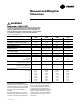
Electrical Requirements Table E1: VUV 075-150, Electrical Performance Model No.
Electrical Requirements Table E1: VUV 075-150, Electrical Performance (continued) Model No.
Pre-Start Checklist Pre-Start-up Checklist Before energizing the unit, the following system devices must be checked: ____ Is the high voltage power supply correct and in accordance with the nameplate ratings? ____ Is the field wiring and circuit protection the correct size? ____ Is the low voltage control circuit wiring correct per the unit wiring diagram? ____ Is the piping system clean/complete and correct? ____ Is unit serviceable? (See clearance specifications on page 7).
Maintenance ! WARNING Hazardous Service Procedures! The maintenance and troubleshooting procedures recommended in this section of the manual could result in exposure to electrical, mechanical or other potential safety hazards. Always refer to the safety warnings provided throughout this manual concerning these procedures. When possible, disconnect all electrical power including remote disconnects before servicing.
Maintenance ! WARNING Hazardous Service Procedures! The maintenance and troubleshooting procedures recommended in this section of the manual could result in exposure to electrical, mechanical or other potential safety hazards. Always refer to the safety warnings provided throughout this manual concerning these procedures. When possible, disconnect all electrical power including remote disconnects before servicing.
Maintenance ! WARNING Hazardous Service Procedures! The maintenance and troubleshooting procedures recommended in this section of the manual could result in exposure to electrical, mechanical or other potential safety hazards. Always refer to the safety warnings provided throughout this manual concerning these procedures. When possible, disconnect all electrical power including remote disconnects before servicing.
Warranty Information Warranty Information Standard Warranty The standard unit ventilator warranty is Trane’s parts-only warranty, running 12-months from startup, not to exceed 18-months from shipment. Extended Warranty The optional extended warranty is a second through fifth year warranty. The time starts at the end of standard 1-year coverage through the fifth year.
Trouble Shooting Checklist ! WARNING Hazardous Service Procedures! The maintenance and trouble shooting procedures recommended in this section of the manual could result in exposure to electrical, mechanical or other potential safety hazards. Always refer to the safety warnings provided throughout this manual concerning these procedures. When possible, disconnect all electrical power including remote disconnects before servicing.
Trouble Shooting Checklist Problem Heating Cooling X X Cause Room sensor is not properly set Clogged filter Replace filter X Face and bypass damper, or coil valve is malfunctioning. Replace malfunctioning component, or contact the control’s contractor, or if Trane controls, see CNT-SVX04A-EN for more information concerning Tracer™ controls. X OA damper is in the open position Ensure OA damper is in the closed or minimum outside air position.
Unit Wiring Field Installed Wiring 120V/1 PH - 3-Speed UV-SVN03D-EN 33
Unit Wiring End Device Controls 120V/1 PH - 3-Speed, DX/Hot Water 34 UV-SVN03D-EN
Unit Wiring End Device Package 480V/3 PH - 3-Speed, Chilled Water/Electric Heat (6-Element) -page 1 UV-SVN03D-EN 35
Unit Wiring End Device Package 480V/3 PH - 3-Speed, Chilled Water/Electric Heat (6-Element) -page 2 36 UV-SVN03D-EN
Unit Wiring End Device Package 120V/1 PH - 3-Speed, 4-Pipe Hot Water/Chilled Water UV-SVN03D-EN 37
Unit Wiring Tracer ZN520 120V/1 PH - 3-Speed, 4-Pipe Hot Water/Chilled Water 38 UV-SVN03D-EN
UV-SVN03D-EN 39
Literature Order Number UV-SVN03D-EN Date October 2007 Supersedes UV-SVN03C-EN May 2006 Trane A business of American Standard Companies www.trane.com For more information, contact your local district office or e-mail us at comfort@trane.com Trane has a policy of continuous product and data improvement and reserves the right to change design and specifications without notice.