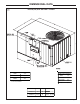
INSTALLATION OPERATION MAINTENANCE ALL phases of this installation must comply with NATIONAL, STATE AND LOCAL CODES Model: YCZ036F1/3M0B, 4MOA YCZ050F1/3HOA, 4H0A YCZ060F1/3M0B, 4M0A BAYLIFT002A LIFTING LUG KIT YCZ-IOM-1F 18-EB21D4-7 Library Product Section Product Model Literature Type Sequence Date File No.
GENERAL INFORMATION IMPORTANT: Read this entire manual before beginning installation procedures. ▲WARNING: BODILY INJURY CAN RESULT FROM HIGH VOLTAGE ELECTRICAL COMPONENTS, FAST MOVING FANS, AND COMBUSTIBLE GAS. FOR PROTECTION FROM THESE INHERENT HAZARDS DURING INSTALLATION AND SERVICING, THE ELECTRICAL SUPPLY MUST BE DISCONNECTED AND THE MAIN GAS VALVE MUST BE TURNED OFF.
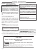
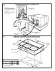
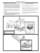
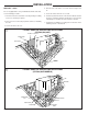
1 TYPICAL ROOFTOP INSTALLATION WITH FULL PERIMETER CURBS (YCZ036,050,060F Models) FIELD SUPPLIED SUPPORTS AT EACH END OF CURB ROOFING ROOF INSULATION FIELD SUPPLIED CANT STRIP ROOF DECK FIELD SUPPLIED RIGID INSULATION ROOF MOUNTING CURB SUPPLY AIR DUCT 2 RETURN AIR DUCT TYPICAL ROOFTOP INSTALLATION WITH BAYCURB030A,038A (YCZ036,050,060F Models) SEE NOTE 1 SEE NOTE 2 FIELD SUPPLIED SUPPORTS AT EACH END OF CURB ROOFING ROOF INSULATION FIELD SUPPLIED CANT STRIP ROOF DECK FIELD SUPPLIED RIGID INSULATI
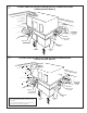
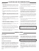
DIMENSIONAL DATA 3 YCZ036,050,060F OUTLINE – BACK CORNER WEIGHT (LBS) MODEL W1 NET UNIT WEIGHT (LBS) W2 W3 W4 YCZ036F 161 106 104 157 528 YCZ050F 172 121 137 196 626 A B 64 36 29-3/16 18-9/16 11-1/16 6-9/16 11-1/8 Page 4 132 199 656 D E F G H 17 J K L 18-1/2 25-1/2 17-1/2 24 65-1/8 45 YCZ060F 195 129 C M N P 10 3 8-3/4 26-1/2 33-3/8 21-1/16 15-1/16 4-15/16 9-1/8 21-15/16 20 22-3/4 25-1/2 14 3-1/2 8-5/16
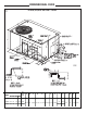
DIMENSIONAL DATA 4 YCZ036,050,060F OUTLINE – FRONT CLEARANCE TO COMBUSTIBLE MATERIAL BOTTOM 0.0" RECOMMENDED SERVICE CLEARANCE BACK * 6.0" LEFT SIDE 30.0" BACK 1.0" RIGHT SIDE 24.0" FRONT 42.0" LEFT SIDE RIGHT SIDE 6.0" 6.0" * 18" WITH FRESH AIR ACCESSORY * 30" WITH ECONOMIZER MODEL A B C D YCZ036F-M 64 36 29-3/16 27-1/2 YCZ050F-M YCZ060F-M 65-1/8 45 33-3/8 27-15/16 FRONT SIDE 12.0" TOP 36.
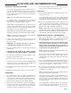
5 CONVERTING HORIZONTAL TO DOWNFLOW NOTE SUPPLY OPENING 1. REMOVE SCREW NEAREST TO THE OPENING AND PULL THE PANEL FIRMLY TOWARD THE OUTSIDE OF THE UNIT TO DISENGAGE THE BACK ATTACHMENT. HEATER EXCHANGER TUBES RETURN OPENING 2. REMOVE RIGHT HAND SCREW AND MOVE PANEL TO THE RIGHT OR REMOVE BOTH SCREWS.
LOCATIONS AND RECOMMENDATIONS HORIZONTAL AIRFLOW APPLICATION 1. These units are design certified for outdoor installations. These units may be installed directly on wood flooring or on Class A, Class B, or Class C roof covering material. The discharge air from the condenser fans must be unrestricted for a minimum of 3 feet above the unit. NOTE: The unit is shipped for horizontal installation.
LOCATIONS AND RECOMMENDATIONS continued from page 7 Examine all flue product-carrying areas of the furnace, its vent system, and the main burner for safe operation. A periodic inspection of the furnace should be made at the start of each heating season. Replacement parts list for this Gas/Electric Air Conditioner may be obtained by contacting your local manufacturer representative. 6. Location of the unit must allow for service clearance around it. Clearance of the unit must be given careful consideration.
INSTALLATION IMPORTANT: Do not lift the unit without test lifting for balance and rigging. Do not lift the unit in windy conditions or above personnel. Do not lift the unit by attaching a clivus, hooks, pins, or bolts to the unit casing, casing hardware, corner lugs, angles, tabs, or flanges. Failure to observe these warnings may result in equipment damage. 4. When the curb and air ducts have been properly installed, the unit is ready to be hoisted to the roof and set in position.
INSTALLATION ROOFTOP -- UNITS 4. Place the unit on the frame or roof curb. Refer to Figures 9 or 10. For roof top applications using a field fabricated frame and ducts, use the following procedure: 1. The frame must be located and secured by bolting or welding to the roof. Flashing is required. 2. The hole in the roof must be prepared in advance of installing the unit. 5. Secure the unit to the frame or roof curb. 6.
INSTALLATION GROUND LEVEL -- HORIZONTAL UNITS 2. Attach the supply and return air ducts to the unit. For ground level installations, the unit should be positioned on a pad the size of the unit or larger. The unit must be level on the pad. The pad must not come in contact with the structure (See Figure 11.) Be sure the outdoor portion of the supply and return air ducts are as short as possible. 3. Insulate any ductwork outside of the structure with at least 2 inches of insulation and weatherproof.
DUCTWORK ATTACHING DOWNFLOW DUCTWORK TO ROOF CURB ATTACHING HORIZONTAL DUCTWORK TO UNIT Supply and return air flanges are provided on the roof curb for easy duct installation. All ductwork must be run and attached to the curb before the unit is set into place. All conditioned air ductwork should be insulated to minimize heating and cooling duct losses. Use a minimum of two (2) inches of insulation with a vapor barrier. The outside ductwork must be weatherproofed between the unit and the building.
GAS PIPING INSTALLATION CAUTION: Before making the gas pipe connection give serious consideration to providing the required clearance necessary to remove the access panels on the unit (e.g., economizer and filter access panels). NOTE: If this is an LPG application, consult your LPG supplier for pipe sizes and deliveries. GAS PRESSURE SETUP PRECAUTIONS NOTE: In the absence of local codes, the installation must conform with American National Standard--Z223.1--National Fuel Gas Code, Latest Revision.
GAS PIPING INSTALLATION NOTE: The shut-off gas cock must be installed outside of the unit and should meet the specifications of all applicable national and local codes. 2. Install a ground union joint downstream of the shut-off cock. This joint must also be installed outside of the unit. 3. Install a drip leg at least six (6) inches in depth next to the union as shown in Figure 14. This drip leg is required to collect any sediment that may be deposited in the line.
GAS PIPING INSTALLATION INPUT CHECK AND ADJUSTMENT TABLE 3 1. Make sure all gas appliances are off except the furnace. 2. Clock the gas meter with the furnace operating (determine the dial rating of the meter) for one revolution. 3. Match the “Sec” column in the gas flow (in cfh) Table 3 with the time clocked. 4. Read the “Flow” column opposite the number of seconds clocked. 5. Use the following factors if necessary. For 1 Cu. Ft. Dial Gas Flow CFH = Chart Flow Reading / 2 For 1/2 Cu Ft.
FILTER INSTALLATION AIR FILTERS TABLE 4 Filters are to be used with the YCZ036,050,060F heating/cooling units. The basic unit does not have filters in it. However, a filter frame accessory is offered that will allow filters to be installed within the unit. Otherwise a filter rack must be installed by the installer in the duct work. Affix the filter label supplied with the unit adjacent to the filter area. UNIT NOMINAL CFM FILTER* Sq.Ft.- SIZE FILTER RESISTANCE YCZ036F 1200 4 0.
ELECTRICAL WIRING After all electrical wiring is complete, set the thermostat system switch in the OFF position so that the compressor will not run and then apply power by closing the system main disconnect switch. This will activate the compressor sump heat. Do not change i the Thermostat System Switch until power has been applied long enough to evaporate any liquid R-22 in the compressor. It is recommended that the sump heater be energized for eight (8) hours prior to starting.
START - UP PRE-START QUICK CHECKLIST ● Is the unit properly located and level with the proper clearance? See Figure 4. ● Is the duct work correctly sized, run, taped, insulated, and weatherproofed with proper unit arrangement? See Ductwork Installation section. NOTE: Do not use the pressures from the unit's SERVICE FACTS to determine the unit refrigerant charge. The correct charge is shown on the unit nameplate. To charge the system accurately, weigh in the charge according to the unit nameplate.
START - UP 8. Set the thermostat at the desired temperature setting and the unit will function automatically. STARTING THE UNIT IN THE GAS HEATING MODE 1. Check to make sure all grilles and registers are open and all unit access doors are closed before start-up. 2. Purge the gas supply line of air by opening the union ahead of the unit. When the odor of gas is detected, retighten the union and wait five (5) minutes before proceeding. 3.
SEQUENCE OF OPERATION The rollout switch (FS) is located in the gas compartment near the inlet of the burners. This is a single use device designed to protect against any form of flame rollout. If this device is opened the gas valve is immediately de-energized and the control (IGN) will lockout the system. The rollout switch (FS) must be replaced before operation is allowed to continue. The pressure switch (PS) is located in the upper right side of the gas compartment.
IGN LED DIAGNOSTIC INDICATOR FLASHING SLOW NORMAL CALL FOR HEAT CONTINUOUS ON NORMAL CONTINUOUS OFF CHECK POWER / INTERNAL FAILURE 2 FLASHES SYSTEM LOCKOUT ( NO FLAME ) 3 FLASHES PRESSURE SWITCH PROBLEM 4 FLASHES HIGH LIMIT (TCO) OPEN 5 FLASHES FLAME SENSED WITH GAS VALVE OFF 6 FLASHES FLAME ROLLOUT SWITCH (FL) OPEN 7 FLASHES W1 & W2 SWAPPED CHECKOUT PROCEDURE p TROUBLESHOOTING CHART SYSTEM FAULTS REFRIGERANT CIRCUIT Liquid Pressure Too high Liquid Pressure Too Low Suction Pressure Too
MAINTENANCE ROUTINE MAINTENANCE BY OWNER You can do some of the periodic maintenance functions for your YCZ-F unit yourself; this includes replacing the disposable or cleaning the permanent air filters, cleaning the unit cabinet, cleaning the condenser coil, and conducting a general unit inspection on a regular basis. When the system is in constant operation. In new homes, check the filters every week for the first four (4) weeks.
LIMITED WARRANTY COMBINATION GAS ELECTRIC AIR CONDITIONER YCZ, YCY AND YCX Models Less Than 20 Tons for Residential Use* (Parts Only) This limited warranty is extended by American Standard Inc., to the original purchaser and to any succeeding owner of the real property to which the Combination Gas Electric Air Conditioner is originally affixed, and applies to products purchased and retained for use within the U.S.A. and Canada.
LIMITED WARRANTY COMBINATION GAS ELECTRIC AIR CONDITIONER YCZ, YCY, YCX, YCC, YCD, YCH, YCP, YHC and YSC Models Less Than 20 Tons for Commercial Use* (Parts Only) his warranty is extended by American Standard Inc., to the original purchaser and to any succeeding owner of the real property to which the Combination Gas Electric Air Conditioner is originally affixed, and applies to products purchased and retained for use within the U.S.A. and Canada.