Ffirm Atlas5010™ Point-to-Point Wireless Ethernet Bridge USER MANUAL June, 2007 Revision 3.
Preface FCC Information Table of Contents Preface...................................................................................................................................................................iv FCC Information .......................................................................................................iv Warranty Information ...............................................................................................iv Contact Information..................................
Preface FCC Information Upgrade Procedure ................................................................................................. 32 Example 1 Upgrade main image firmware to 1.0a6 .................................................. 33 Example 2 Upgrade web firmware to 1.0a6 ............................................................. 33 Appendix A Using the HTTP Interface.........................................................................................................
Preface FCC Information Preface This manual covers the basic configuration and installation of the Atlas5010 Wireless Point to Point Broadband System, and applies to the following radio part numbers: P5010M-INT P5010M-EXT Unit with internal patch antenna Unit with external antenna connectors The Atlas5010-INT consists of two P5010M-INT radios which have internal 23 dBi antennas.
Preface Contact Information Contact Information Corporate Headquarters Web Sites Sales Inquiries Technical Support Firmware Update Notices Mailing List Trango Broadband Wireless — Atlas-45 Trango Broadband Wireless, a division of Trango Systems, Inc. 15070 Avenue of Science Suite 200 San Diego, CA 92128 USA www.trangobroadband.com www.trangosys.com email: sales@trangobroadband.com Telephone: 1-858-653-3900 email: techsupport@trangobroadband.com Telephone: 1-858-653-3900 http://www.trangobroadband.
Overview OFDM Chapter 1 Overview The Atlas5010 is a point-to-point (PtP) wireless Ethernet transmission system which provides network connectivity at speeds up to 45 Mbps depending on the transmission distance and noise floor. The Atlas5010 utilizes OFDM technology and is designed for use in long range backhaul and wide area data networking applications. Users are required to simply specify one P5010M (INT or EXT) unit type as master unit (MU) and one unit as remote unit (RU).
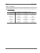
Overview Range vs. Throughput Range vs. Throughput The following table shows approximate maximum ranges (at recommended fade margins) achievable with the Atlas5010 system using various antenna configurations. Longer ranges are achievable, but will result in lower fade margins. To estimate theoretical throughput and fade margin for any distance, download the link budget / fade margin calculator tool from www.trangobroadband.com .
Overview System Contents System Contents The Atlas5010 system is available in two versions: Atlas5010-INT Atlas5010-EXT - Radios with integrated 23 dBi antennas (part numbers P5010-INT) Connectorized radios (part numbers P5010-EXT) Each Atlas5010 kit consists of two radios, two power-over-Ethernet (PoE) injectors, two AC adapters, port covers, and mounting hardware. A dual-polarized integrated antenna is located behind the radome of the P5010M-INT.
Overview Location of Serial Number & MAC Address Location of Serial Number & MAC Address The serial number and MAC address label can be found on the back of each radio. The serial number and MAC address is also provided within the system information (sysinfo) screen. Trango Broadband Wireless P5010M- INT Rev.
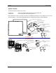
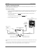
Getting Started Connections and Power Chapter 2 Getting Started It is always a good idea to first provision and test the radios on the bench before deploying them in the field. This is a particularly useful exercise for the novice user. Connections and Power • Connect a Cat-5 (straight through) Ethernet cable (we recommend shielded twisted pair) between the ODU (out door unit) port of the J-box and the RJ-45 connector on the radio. Note that this cable will carry power-overEthernet (PoE).
Getting Started Configuration Tools Configuration Tools Atlas5010 radios can be configured using either the Command Line Interface (CLI), or the Web Browser (HTTP) interface. The CLI method provides slightly more functionality. This text covers configuration through the CLI. For HTTP configuration please see Appendix A. Telnet Open a command prompt (DOS) session on your PC. Open a Telnet session by typing: telnet Example: C:>telnet 192.168.100.
Getting Started Troubleshooting Ethernet Connections Troubleshooting Ethernet Connections If you cannot telnet into the radio or open an HTTP browser session, check your cable connections to ensure proper use of cross-over vs. straight-through cable, and ensure your PC’s subnet is routable to the radio’s IP address. System Information (sysinfo) Page To display system configuration and status information type the command sysinfo.
Getting Started System Information (sysinfo) Page Sysinfo Example: #> sysinfo ********************************* 0 ********************************* [Model] P5010M [Unit Type] MU [Hardware Version] 5010 [Firmware Version] 3p0r1D07061901 [System Up Time] 1 day(s) 21:52:14 ********************************* 1 ********************************* [MAC] 00 01 DE FF FF F3 [S/N] 16777203 [IP] 10.8.2.138 [Subnet Mask] 255.255.255.224 [Gateway] 10.8.2.
Getting Started System Information (sysinfo) Page [Eth In] 55,256,030 bytes 24 Kbps [Eth Out] 3,348,202 bytes 3 Kbps [RF In] 1,377,125 bytes 0 Kbps [RF Out] 45,499,374 bytes 44 Kbps [ARQ Retransmission] 881 pkts Success. #> To view only a particular section of the sysinfo screen, type sysinfo followed by the desired section number. Example: #> sysinfo 2 ********************************* 2 ********************************* [Radio Temp] 32 C [PoE Voltage] 14.
Getting Started System Information (sysinfo) Page Section 3 Channel Table: (MHz, n/a: not available in current area) [Ch#01] 5700 n/a [Ch#02] 5700 n/a [Ch#03] 5700 n/a [Ch#04] 5700 n/a [Ch#05] 5700 n/a [Ch#06] 5700 n/a [Ch#07] 5700 n/a [Ch#08] 5700 n/a [Ch#09] 5700 n/a [Ch#10] 5700 n/a [Ch#11] 5700 n/a [Ch#12] 5700 n/a [Ch#13] 5700 n/a [Ch#14] 5700 n/a [Ch#15] 5700 n/a [Ch#16] 5700 n/a [Ch#17] 5700 n/a [Ch#18] 5840 n/a [Ch#19] 5735 [Ch#20] 5755 [Ch#21] 5775 [Ch#22] 5795 [Ch#23] 5815 [Ch#24] 5835 Section 4
Configuration Key Concepts Chapter 3 Configuration Key Concepts Prior to configuring the radios it is important to understand several key concepts: Master Unit (MU) The MU is typically considered the primary radio within the link. For management purposes it is recommended to install the MU closest to the head-end of the network. Remote Unit (RU) The RU is typically installed at the remote end of the link.
Configuration 2. Remote Unit Configuration Set the Peer ID with the MAC address of the RU. Only use the last 8 digits of the MAC address. #> peerid de1B7850 Success. #> 3. Set channel and polarization. (in this example set the channel to 2 and polarization to H). #> freq 20 v Ch# 20 v (5775 MHz) Success. 4. Set default Opmode to ON. #> defaultopmode on Success. 5. Turn Opmode ON. #> opmode on Success. . Remote Unit Configuration Configure the RU in the same manner as the MU.
Configuration Changing IP Address [Speed] 54 Mbps [Tx Power] 17 dBm [Power Range] -4..17 dBm [Peer ID] DE1B7747 [Status] connected [RSSI] -44 dBm [Peer IP Config] 10.8.2.139 255.255.255.224 10.8.2.129 Success. The [status] field indicates whether the MU and RU are connected or disconnected. If connected, the MU and RU will automatically start passing Ethernet traffic over the wireless link. Changing IP Address Use the ipconfig command to change the radio’s ip address, subnet mask and gateway.
Configuration RF Link Loopback Test (linktest command) In addition, these 4 LEDs shall flash ON for 2 seconds, then OFF for 2 seconds to indicate the 'factory reset' button has been activated and the reset successful. ASSOCiation LED (green): The ASSOC led blinks at the following rates: - Once every second when unit is powered on but opmode is OFF. - Twice per second while in opmode ON and scanning for an MU or RU. - Solid after unit is associated with the RU or MU.
Configuration Link Speed & Power Settings Link Speed & Power Settings Users may change the radio’s over-the-air data rate and conducted output power using the speed and power commands. Keep in mind that the lower data rates offer higher receiver sensitivity and higher allowable conducted RF power in the ISM band. The following table shows the relation between speed settings, modulation scheme, receiver sensitivity, and allowable maximum power settings for each band.
Configuration Automatic Rate Shifting Feature Description Automatic Rate Shifting Feature Description With autorateshift feature enabled, the radios will automatically renegotiate the modulation method and speed speed to maximize wireless link integrity. The link speed will vary depending on two factors: 1) the number of ARQ errors received, 2)successful processing of special link assessment packets sent in both the current and next higher speed.
Configuration MIR Feature Description MIR Feature Description Maximum Information rate is configurable on both the MU and RU. The MIR function is performed on the transmit side only and is based on a one second timing interval. During each one second timing interval, the total bits transferred is compared to the MIR limit configured by the user. When the limit is exceeded, no more data is sent and the packets in the queue will be dropped.
Configuration Command Reference Listing Command Reference Listing The complete command set reference is provided below. You can also view a complete listing of all CLI commands by typing help. Command Syntax antenna [h|v] arq [on|off] autorateshift [on|off] Description Set or display antenna setting. H=Horizontal polarity, V=vertical polarity. Enable or disable Auto Retransmit Request (ARQ). With ARQ enabled, the Atlas system will retransmit packets which are detected as missing or corrupted.
Configuration defaultopmode [on|off] encrypt [on|off] encrypt key exit freq [ ] freq writechannel … freq writechannel default help [] ipconfig [ ] linktest [ [<# of pkt> [<# of cycle>]]] Command Reference Listing Set or display default opmode. Radio must be set to opmode ON to establish wireless link. Default setting=OFF Enable or disable proprietary 128 bit tx encryption.
Configuration sysinfo [[ [ [..]]]] syslog tftpd [on|off] utype [mu|ru] Trango Broadband Wireless — Atlas5010 Command Reference Listing Display system information and status = 0..6 part 0: up time and version information part 1: MAC address and IP configuration part 2: RF link status part 3: channel table part 4: region code and power limitations part 5: switch settings and remarks part 6: statistics Display system log. Enable or disable tftpd (used for firmware upgrades).
Deployment & Installation Site Selection Chapter 4 Deployment & Installation Once you are familiar with the basic operation of the radios you are ready for deployment in the field. The deployment process consists of the following steps: • Site Selection • Site survey at MU and RU sites • MU installation • RU installation and antenna alignment • Link test Site Selection Proper site selection for your MU will help ensure a successful deployment.
Deployment & Installation Ch 23 h 5815 Ch 23 v Ch 24 h 5835 Ch 24 v Success. : : : : Channel Planning -98 -98 -98 -98 / / / / -98 -98 -98 -98 n/a n/a n/a n/a / / / / n/a n/a n/a n/a Channel Planning Based on the results of the site survey at each end of the link, choose a channel which offers the lowest noise floor. In order to reliably operate in the higher speed modes, clean spectrum is essential.
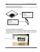
Deployment & Installation Port Plug and Port Plate (Hardware) Port Plug and Port Plate (Hardware) Prior to deployment, insert the silicone port plug around the Cat-5 Cable and insert into the radio’s port opening. Next, screw the port plate over the silicone plug as shown in the photographs below. Mounting Hardware Radios are supplied with mounting hardware for pole installations. See diagram below for proper use of the mounting hardware. 8.50 MAX 10.00° UPTILT 25.
Deployment & Installation Trango Broadband Wireless — Atlas5010 Connecting External Antenna on EXT Model page 29
Deployment & Installation Cat-5 Cabling Considerations Cat-5 Cabling Considerations Shielded twisted pair Cat-5 cable is recommended for all installations. The shield within the Cat-5 cable does not need to be grounded if the radio itself is grounded. It is important to consider that most Cat-5 cable will deteriorate over time if exposed to the weather (especially direct sunlight). It is recommended that installers place all Cat-5 cables inside conduit. Plastic conduit is sufficient.
SNMP Atlas SNMP Support Chapter 5 SNMP Atlas SNMP Support The Atlas supports SNMP (Simple Network Management Protocol). Network management consists of the following 3 categories: configuration, Link and Association monitoring and Alarms. Besides this proprietary Management Information Base (MIB) the Atlas also supports a large part of the MIB-II OIDs. Review the Trango MIB (TRANGO-P5M-MIB.mib) available on our website for the complete listing of all MIB objects available.
Firmware Upgrade Procedure Firmware File Names Chapter 6 Firmware Upgrade Procedure Trango Broadband Wireless will from time to time release firmware upgrades for the Atlas series radios. The latest released firmware can be downloaded from http://www.trangobroadband.com/support/downloads.htm. Firmware releases consists of two files: Main image firmware and Web (HTTP interface) firmware. Firmware File Names Firmware files are released in the format shown below.
Firmware Upgrade Procedure Example 1 Upgrade main image firmware to 1.0a6 Example 1 Upgrade main image firmware to 1.0a6 FROM RADIO TELNET SESSION Welcome to Trango Broadband Wireless, Atlas PtP-P5010M 3p0r1D07061901 Password: Login as read/write. #> tftpd on Success. #> FROM COMPUTER COMMAND PROMPT SESSION C:\Atlas>dir Volume in drive C is Local Disk Volume Serial Number is 7802-AAF7 Directory of C:\Atlas 06/28/2007 06/28/2007 06/28/2007 06/28/2007 02:47 PM
. 02:47 PM ..Appendix A Command Set Reference Appendix A Using the HTTP Interface Open a browser session and type in the IP address of one of the radios. Default IP address is 192.168.100.100. Leave the User name field blank and enter read write or read only Password. Press OK. Default password is trango. After logging on, the system information screen will be displayed.
Appendix A Command Set Reference Navigation links are shown on the left side of the browser screen. Navigable links include: System Information Configuration Site Survey Link Control Help The lower left portion of the screen shows the unit’s current opmode, connection, channel, and antenna status. The main body of the System Information displays most of the key parameters. To alter these parameters use the Configuration page.
Appendix A Command Set Reference Description of System Information entries. To view this information within the radio, click the Help link. Model: Model number. Unit Type: Atlas unit type either MU (master) or RU (remote). Hardware Version: Hardware version is factory-set and can not be changed by user. Firmware Version: Current firmware version loaded in the radio. System Up Time: Time since radio was last rebooted or powered. MAC: MAC address of the radio.
Appendix A Command Set Reference RF In: Counter for Ethernet packets which entered over-the-air into the radio. RF Out: Counter for Ethernet packets which exited over-the-air out the radio. Configuration Page IP Address: The IP address of this radio; used to manage the radio's application layer. Subnet Mask: The subnet mask of the radio. Gateway: The default gateway of the radio. Default Opmode: Operation mode of the radio after power cycle.
Appendix A Command Set Reference Activate Opmode Off: Activates radio's Opmode to "Off" not-transmitting. Reboot: Reboot the unit. Close All Telnet Sessions: Close all the active telnet sessions.
Appendix A Command Set Reference All user configurable parameters can be entered from the Configuration Screen and this is the only screen used to provision a wireless link between the two radios. Configuration Screen – Minimum Required Settings to Establish a Wireless Link To configure a wireless link, user must (at a minimum) enter the following information: Unit Type: Set one radio as the MU and one radio as the RU. Click on “Change Unit Type” to save the setting.
Appendix A Command Set Reference Connection Status Trango Broadband Wireless — Atlas5010 page 40
Appendix A Command Set Reference Site Survey Page The site survey function measures overall noise floor as well as in-band noise containing data packets. Noise is reported in terms of average and peak dBm for the period tested. The user specifies duration of the test in minutes as well as the antenna port. To run a site survey, the radio must be in Opmode OFF. In this example the site survey function was performed for 1 minute on the vertical polarity.
Appendix A Command Set Reference Link Control The Link Control page features the RF Link Loopback / Speed Test. In this test, the user specifies the transmission rate (in Mbps) in both the local radio and the peer radio as well as the duration time (in minutes) for the test. During the test, the local radio will transmit packets across the wireless link. The peer radio will retransmit equivalent packets back to the local radio.
Appendix B Specifications Appendix B Specifications RF Parameters Transmitter RF Conducted Power: Limits Band 4 (US ISM): 5.725-5.
Appendix B Specifications Data Parameters Format: 10/100 BaseT IEEE 802.3 Ethernet compliant Ethernet packet: Up to 1518 byte packets Regulatory Compliance FCC Standards FCC 15.109 FCC 15.203 Antenna FCC 15.207 FCC 15.209 FCC 15.
Appendix B Specifications Antennas Integrated Antenna (for Atlas5010-INT) Frequency range: 5250-5850 MHz Gain: 23 dBi +/- 1 dB Front/Back Ratio >35 dB E-Plane Beamwidth: > 9 degrees typical H-Plane Beamwidth: > 9 degrees typical Polarization: Vertical and Horizontal Port/Port Isolation: 40 dB typ Cross Pol Rejection: 25 dB typ VSWR: <1.7:1 Package: Alumininum backplate with plastic radome. Dimensions: 14.6”x 14.6”x 1.58” (371mm x 371mm x 40mm) Weight: 5.5 lbs (2.