
User Manual


Copyright © 1999 Sunstream Wireless, LLC All rights reserved.
7
1) Keep the transmission path as open as possible. Objects such as walls and metallic
objects near the transmission path reflect signals and may reduce the transmission
distance.
2) Do not add additional lengths of cable to connect the to the antenna as significant
losses in signal and reduced transmission range will occur.
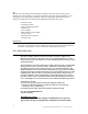
3) Mount the transceiver on the dish mounting pole as shown in Figure 1.
4) Connect the antenna cables, paying attention to the polarization shown on the feed.
IMPORTANT NOTE: The transmitter uses a non-standard jack to connect to
the transmitter antenna. Any modification to this jack may void the user’s
authority to operate the equipment and will void the manufacturer’s warranty.
5) Connect the STP run no longer than 150 feet – Use straight through 8 conductor cat 5
cable, making sure that the RJ45 terminations are shielded.
6) Use standard outdoor to indoor drip loop and grounding per National Electrical Code
and electrical conduit if appropriate.
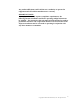
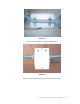
7) Connect the Junction Box to an interior wall near the entry point of the cable.
8) Plug the STP cable into the ODU port of the Junction Box.
9) Plug the wall mount power adapter into the Junction box.
10) Plug the wall mount adapter into the wall outlet.
11) The LEDs on the Junction box should both be on, indicating that the power is coming
into the junction box properly and that the outdoor transceiver is powered up properly.
Check the wiring if this is not the case.
ANTENNA ALIGNMENT
Once the power to the transceiver is verified, align the antenna by aiming it towards the
base station until the yellow LED blinks as fast as possible or turns completely solid. This
indicates a very strong signal from the base station. If the Yellow LED is lit up at all, the
signal is not being received or the antenna is aimed far away from the base station. The
beamwidth of the antenna is about 7 degrees, so small movements of the antenna can
create large changes in signal strength.
CONNECTION VERIFICATION
After the alignment is completed, an Ethernet cable can be connected to the “NET” port
of the Junction Box and then to a switched hub or PC network card. A crossover cable
will be required if connecting to a PC NIC.
CAUTION CAUTION DO NOT APPLY POWER TO THE TRANSCEIVER WITHOUT
THE ANTENNA SECURELY ATTACHED.