
User's Manual


TrangoFOX™ Subscriber Unit User Manual
Trango Broadband Wireless
Page 6
Getting Started
It is recommended to first provision and test the radio on the bench before deploying in the field. This is a particularly useful
exercise to the novice user.
Connections and Power
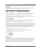
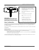
• Remove the “boot” and Foam Insert from the bottom of the radio.
• Connect a Cat-5 (straight through) Ethernet cable (we recommend shielded twisted pair) between the ODU (out door
unit) port of the J-box and the RJ-45 connector on the radio. Note that this cable will carry power over Ethernet
(PoE).
• If connecting to a COMPUTER, use a Cross-Over Ethernet cable from the NET port of the J-box to the computer’s
Ethernet port.
If connecting to a HUB, SWITCH, or ROUTER, use a Straight-Thru cable.
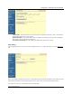
• Plug the AC adapter into an AC outlet.
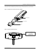
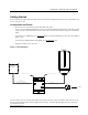
Figure 5. Wiring Diagram
CAT-5
STRAIGHT-THRU CABLE
20 VOLT POWER
SUPPLY
AC POWER
FOX RADIO
POWER OVER ETHERNET
J BOX
INDICATES POWER TO RADIO
INDICATES POWER TO J BOX
NETWORK
OR
COMPUTER
USE STRAIGHT-THRU CABLE
USE CROSS-OVER CABLE IF TO COMPUTER
IF TO HUB, SWITCH OR ROUTER
CAT-5
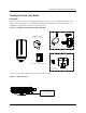
Once the radio is powered, check the LED lights on the bottom of the unit for status information. If the unit is powered,
and not associated with an AP, the ASSOC light should be blinking. The NET LED will light if the unit is connected
to a 100 Base-T Network.