Access5830™ Wireless Broadband System USER MANUAL June, 2007 Revision H 3.0 Trango Broadband Wireless — Access5830 User Manual Rev. H 3.
Table of Contents Trango Table of Contents Table of Tables .......................................................................................................... iv Section 1 Preface ........................................................................................................ v FCC Information.............................................................................................................................................................................. v Warranty Information....
Table of Contents Trango Appendix D RF Primer ................................................................................................ 69 Glossary .................................................................................................................. 74 Trango Broadband Wireless — Access5830 User Manual Rev. H 3.
Table of Figures Trango Table of Figures Figure 2-1: Typical Point-to-Multipoint Deployment............................................................................................................................ 1 Figure 3-1: Access5830 Series Radios (AP and SU) .......................................................................................................................... 3 Figure 3-2: FOX Series Subscriber Units ..............................................................................
Preface Section 1 FCC Information Preface This manual covers basic configuration and installation of the Access5830 Wireless Broadband System, and applies to the following radio part numbers: M5830S-AP-60 M5830S-AP-EXT** M5800S-FSU M5800S-FSU-D M5830S-SU M5830S-SU-EXT** Dual-band Access Point with internal sectoral patch antenna Dual-band Access Point with connector for external antenna FOX5800 5.8 GHz Subscriber Unit FOX5800-D 5.
Introduction Section 2 Overview Introduction Your Trango Broadband Access5830 radio system provides a reliable and robust means to deliver broadband access to a wide geographic region through wireless Ethernet connectivity. This section will familiarize you with basic operational concepts, as well as an overview of the various components and hardware of the Access5830 system.
Introduction SmartPolling™ Overview SmartPolling™ Overview One of the major advantages of the Access5830 system is the ability of the AP to handle multiple SU connections, and share the 10 Mbps data throughput very efficiently. Bandwidth allocation is managed by the AP’s SmartPolling™ algorithm according to provisioning rules set up by the system administrator. The AP polls each SU in a round robin format to determine if the SU has data to transfer.
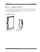
Hardware Overview Section 3 Access5830 Radio Types Hardware Overview This section provides details about each radio in the Access5830 family. Each radio in the Access5830 family includes electronically switchable dual-polarized antennas (internal or external). All units are designed for outdoor installation, and are powered by Power-over-Ethernet (POE) for ease of installation. The Access5830 Access Point and Subscriber Units are single band radios, and provide channels of operation in the 5.
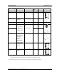
Hardware Overview Access5830 Radio Types Table 1: Access5830 Radio Description Description Freq. Band(s) Access Point M5830S-AP-60 M5830S-AP-EXT Antenna Gain MAX EIRP AP with internal 60° antenna 5725-5850 MHz 14 dBi 36 dBm AP with external connector 5725-5850 MHz N/A N/A 15 dBi 36 dBm 5725-5850 MHz 8 dBi 30 dBm FOX5800-D SU FOX Series 5.8 GHz SU requires AD5800-25 External Dish antenna (Note: this unit will not work without the dish) 5830 Series SU with internal antenna.
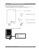
Hardware Overview Access5830 AP and SU Hardware Components Access5830 AP and SU Hardware Components Each radio comes equipped with a power-over-Ethernet (PoE) J-Box, an AC adapter, and mounting hardware. The Access5830 APs (part #M5830S-AP-60, -AP-EXT) also includes a serial programming cable. Figure 3-3: Basic Components of an Access5830 Radio Trango Broadband Wireless M5830S-AP-60 Rev.
Hardware Overview Figure 2-4: Back of Access Point (and 5830 Series SU) Shows Equipment Identification Tag Figure 3-4: Bottom of Access Point (and 5830 Series SU) At the bottom of the Access5830 are two access ports: a twist-on weatherproof cable port for the RJ-45 Ethernet port, and an access cover (port plug for the RJ-11 serial port. Most configuration and management tasks can be performed through the Ethernet port.
Hardware Overview FOX Series Subscriber Units Hardware Components FOX Series Subscriber Units Hardware Components Each FOX series subscriber unit comes equipped with the radio itself, a power-over-Ethernet (PoE) J-Box, an AC adapter, and mounting hardware. The FOX5800 and FOX5300 include hardware for wall or pole mounting (excluding wall mount screws and pole-mount hose clamps). The FOX5800-D is equipped with a dish/reflector mounting bracket.
Hardware Overview FOX Series Subscriber Units Hardware Components FOX RADIO FOAM INSERT BOOT Figure 3-6: Exploded View of Radio, Foam Insert, and Boot TRANGO BROADBAND WIRELESS FOX5800 (TM) M5800S-FSU REV A FCC ID: NCYM5800SFSUD CANADA: XXXXXXXXXX Figure 3-7: Side View of FOX Series SU Trango Broadband Wireless — Access5830 User Manual Rev. H 3.
Hardware Overview FOX Series Subscriber Units Hardware Components M5800S-FSU MAC: S/N: 0001DE FF FF FF XXXXXXXXXX ||||||||||| ||||||||||| ||||||||||| ||||||||||| TEST DATE: XX-XX-XX Figure 3-8: Bottom View of FOX Series SU (Boot Removed) The radio’s model number and FCC ID are located on the side of the radio. The MAC address is on a separate label located under the radio's boot. The TrangoFOX radio is equipped with a removable “boot” and weatherproofing foam insert.
Getting Started Section 4 Connections and Power Getting Started This section explains how to power your radios, establish TCP/IP connectivity to the radios, as well as how to access the HTTP browser and the command line interfaces. Connections and Power Connection and powering of the radios is the same for both APs and SUs. • Connect a Cat-5 (straight through) Ethernet cable (we recommend shielded twisted pair) between the ODU (out door unit) port of the J-box and the RJ-45 connector on the radio.
Getting Started Opmode and Radio Management Concepts Opmode and Radio Management Concepts Proper connections to the radios, and careful IP/routing and planning, will enable the network administrator to access and manage the radios remotely over the network. Radio management through TCP/IP can be performed from a PC connected to the Ethernet port of the radio. Furthermore, PCs connected to the AP can manage SUs over the wireless connection.
Getting Started Browser Interface Browser Interface The HTTP browser interface is an easy-to-use, configuration and management tool. The web pages originate from the radio itself, so no additional software is needed on the managing PC other than a web browser. The browser interface’s functionality is a subset of the commands available in the command line interface (CLI).
Getting Started Browser Interface Figure 4-4: Web Browser System Information Page Figure 3-4 shows the System Information page for an Access Point. Basic system information for a subscriber unit is similar, and is covered in detail later in this text. The following describes the primary features and pages of the HTTP Browser interface: Navigation Column: The blue rectangular column on the left of all pages. The top displays the model number of the radio to which you are connected.
Getting Started Command Line Interface Command Line Interface Although most radio functions can be managed using the browser interface, the command line interface (CLI) does provide slightly more functionality. The CLI can be accessed through Telnet (all radios), or via the serial port (excluding FOX radios). Telnet Open a command prompt (DOS) session on your PC. Open a Telnet session by typing: telnet [] Example: C:>telnet 192.168.100.
Getting Started Command Line Interface Serial Port on M5830 Series Radios M5830 Access Points and Subscriber Units feature a serial port. The serial port is useful in the event that the radio cannot be accessed via TCP/IP (HTTP or Telnet). A Terminal Emulation program (such as HyperTerminal on the Windows operating system) can be used to access the radio’s CLI using the radio’s serial port, which is located behind the RJ-11 access cover on the bottom of the radio.
Basic Configuration via Browser Interface Section 5 Configuring AP’s Subscriber Unit Database Basic Configuration via Browser Interface This section describes a few more basic concepts and how to establish a basic wireless link between the AP and the SU, using the Browser (HTTP) Interface. This section addresses only the most basic steps in establishing a link in the lab, or a bench-top environment.
Basic Configuration via Browser Interface ! Configuring AP’s Subscriber Unit Database 1. Connect to the AP (see Getting Started), and open the Subscriber Database page. 2. Enter the SU ID. 3. Select either PRIORITY or REGULAR. 4. If SU will be part of an SU to SU group, enter the SU to SU group number. Note: SUs using SU to SU communication must be on the same subnet! 5. Enter the SU’s CIR. 6. Enter the SU’s MIR. 7. Enter the SU’s Device ID. 8. Click Save and Activate changes.
Basic Configuration via Browser Interface Configure Other Basic AP Parameters Configure Other Basic AP Parameters In addition to setting up the SU in the SU Database, the following settings from the AP’s Configuration page must be set (or left at default). Base ID: User definable base station ID (1-127); typically assigned to a group of APs at a particular cell site. The Base ID in the AP must match the Base ID in the SU in order for the link to be established.
Basic Configuration via Browser Interface Configure Other Basic AP Parameters Connect to the AP (see Getting Started) and open the Configuration page. 1. Set the Base ID. (Must match the SU.) 2. Set the AP ID. (Used to identify the AP, not essential in establishing a link.) 3. Set the IP, Subnet, and Gateway. (Not essential for a link.) 4. Set the Default Opmode to "AP." 5. Set the Active Channel and Polarization. (Must match at least one set in the SU Scan Table.) 6.
Basic Configuration via Browser Interface Configure Basic SU Parameters Configure Basic SU Parameters Each SU must be set up with basic information to communicate with the AP. At a minimum the Base ID must match the Base ID of the AP, the SU ID must match the SU ID in the AP’s SUDB, and the AP’s active channel must exist in the SU’s AP Scan Sequence. To set up the SU, complete the following steps: 1. Connect to the SU (see Fundamentals), and open the Configuration page. 2. Set the Base ID.
Basic Configuration via Browser Interface LED Summary LED Summary At this point it is useful to learn about the various LEDs, which can be found on the bottom of Access5830 radios (both M5830 series and FOX series). These LEDs can assist the user in determining radio and link status.
Basic Configuration via Browser Interface RF Link Loopback Test Using this page the user can immediately see which SUs have associated. In the page shown, SU ID# 107 is associated, and SU IDs 11, 22, 33, and 44, are not. Consider "Power Off" status synonymous with "not associated." Power leveling takes place automatically every time an SU associates, so in most cases it is not necessary to manually run power leveling. A thorough explanation of this feature is in the Configuration section.
Basic Configuration via Browser Interface Advanced Setup Page Advanced Setup Page The Advanced Setup page includes several important parameters including RF TX Power, RF RX Threshold, and Target RSSI from SU (AP only). This screen also includes the radio’s channel table, which can be configured by the user. Note: M5830 Series radios include the ISM band on this screen. FOX Series radios only include the ISM band. RF TX Power: Sets the conducted RF power output from the radio.
Basic Configuration via Browser Interface Other Key Parameters Other Key Parameters This section describes the remainder of the parameters listed on the System Information page. Most of these parameters are the same for both APs and SUs. Hardware Version: Hardware version is factory-set and can not be changed by user. FPGA Version: Field programmable gate array firmware currently loaded on the radio. Normally the FPGA firmware will not require upgrading. Firmware Version: Main firmware.
Basic Configuration via Browser Interface Site Survey Page Site Survey Page This is a useful tool for detecting interference. It is not meant as a substitute for a Spectrum Analyzer. The radio must be in Opmode "OFF" in order to use this feature. Enter the number of minutes desired for the survey, and select the polarization. Click "Start Survey." A survey of the default 6 channels will be performed. Results are reported in dBm per channel as average and peak.
Basic Configuration via CLI Section 6 Access Point Basic Settings Basic Configuration via CLI It is important for users to be familiar with the CLI interface as well as the Browser Interface. This section covers how to utilize the radio’s CLI interface to establish a working wireless link. Much of the information presented here is similar to the information presented in Section 5. This section covers the most common settings using the CLI.
Basic Configuration via CLI Access Point Basic Settings . Table 2: Reference Table of Basic AP System Information AP SYSTEM INFORMATION PARAMETERS AND RELATED COMMANDS AP Parameter Description Related CLI Command Device ID MAC Address of AP N/A Base ID Specifies the cell or cluster to set baseid which the AP belongs. Base ID is Example: one of three key pieces of #>Set baseid 10 information, along with active channel, and SUDB information for the establishment of a link.
Basic Configuration via CLI AP Parameter MIR Threshold Kbps Active Channel RF RX Threshold RF TX Power Access Point Basic Settings AP SYSTEM INFORMATION PARAMETERS AND RELATED COMMANDS Description Related CLI Command User specified MIR Threshold to set mir threshold [] determine total throughput level at which the AP serves only CIR Example: #>set mir threshold 2000 (committed information rate) to associated SUs. When MIR Threshold is disabled, the AP will serve MIR for all its SUs.
Basic Configuration via CLI Subscriber Unit Basic Settings Subscriber Unit Basic Settings Log into the SU. To receive a comprehensive snapshot of the system’s configuration info and status, type the command sysinfo.
Basic Configuration via CLI SU Parameter Opmode Start IP Subnet Gateway Subscriber Unit Basic Settings SU SYSTEM INFORMATION PARAMETERS AND RELATED COMMANDS Description Related CLI Command #>set defaultopmode ap Opmode “SU” automatically after reboot/power cycle. Determines the amount of time set defaultopmode su [
Basic Configuration via CLI Subscriber Unit Database (SUDB) Settings Subscriber Unit Database (SUDB) Settings Once you are familiar with the AP’s basic system information, you are ready to add one or more SUs to the SUDB. There are three basic commands related to the SUDB: sudb add, sudb view, and save sudb. To add an SU to the database, you will need to know the following information: 1. SU ID (user defined – a unique integer that identifies the SU within this AP’s SUDB) 2.
Mounting Hardware Section 7 M5830 Series Radios (Access Points and Subscriber Units) Mounting Hardware M5830 Series Radios (Access Points and Subscriber Units) Figure 7-1: M5830 Mounting Hardware Assembly Figure 7-2: Alternative Mounting Trango Broadband Wireless — Access5830 User Manual Rev. H 3.
Mounting Hardware Standard Mounting M5830 Series Radios (Access Points and Subscriber Units) Alternative Mounting Figure 7-3: Articulation for M5830S-AP with Mono Pod Mount (not supplied) Trango Broadband Wireless — Access5830 User Manual Rev. H 3.
Mounting Hardware FOX Series Radio Hardware and Mounting FOX Series Radio Hardware and Mounting 1/4-20 X 1" HEX HEAD BOLT FOX RADIO 1"-2" MAST MOUNTING STRAP (2 PLACES) (NOT INCLUDED) 1/4-20 KEP NUT 1/4 EXT. TOOTH WASHER (H-9182) BRACKET (ES-9232) Figure 7-4: FOX Series SU Pole Mount (1” – 2” Diameter) 1/4-20 X1" HEX HEAD BOLT (2 PLACES) EXTENDER (ES-9233) FOX RADIO NOTE: HARDWARE FOR MOUNTING BRACKET TO WALL NOT SUPPLIED BRACKET (ES-9232) 1/4-20 KEP NUT (2 PLACES) 1/4 EXT.
Mounting Hardware FOX Series Radio Hardware and Mounting FOX RADIO FEED ARM FROM 18" OFFSET ANTENNA 1/4-20 X 1" HEX HEAD BOLT DISH MOUNT BRACKET (ES-9231) 1/4-20 KEP NUT 10-32 X 1" PAN HEAD SCREW Figure 7-6: FOX5800-D/Atlas Fox with Mounting Cradle for DSS Dish Antenna 20º APPROX, DOWN TILT FOR 0 º ELEVATION RECEPTION DISH MOUNTED ON MAST USING U-BOLTS FOX RADIO (M5800S-FSU-D / ATLAS FOX) MOUNTED ON DISH Figure 7-7: FOX5800-D / AD5800-25 Reflector Dish on Pole Trango Broadband Wireless — Access
Mounting Hardware Cabling and Grounding Considerations 20º APPROX. DOWN TILT FOR 0º ELEVATION RECEPTION FOX RADIO (M5800S-FSU-D / ATLAS FOX) MOUNTED ON DISH DISH MOUNTED ON WALL (HARDWARE WILL DEPEND ON MATERIAL OF WALL Figure 7-8: FOX5800-D / AD5800-25 Reflector Dish on Wall Cabling and Grounding Considerations Proper mounting of the radio includes consideration for grounding. Please note that if the radio is attached to a metal pole that is earthgrounded, no other grounding is necessary.
Mounting Hardware Cabling and Grounding Considerations CABLE TIE Figure 7-10: Cat-5 Cable Strain Relief It is advised that the radio be grounded through the use of the shielded twisted pair’s drain wires. Prior to crimping the STP Cat-5 cable, strip back approximately 18” of sheathing to expose the drain wires. Cut all wires except the drain wires and then crimp as normal. Ensure that the drain wires make contact with the RJ-45 metal housing.
Mounting Hardware Weatherizing Weatherizing ! Important! If not using a conduit, the Ethernet port compression washer on the 5830 series radios should be loosely tightened around the cat-5 cable to allow pressure equalization within the radio’s enclosure. Leave approximately 1 mm around the Cat-5. ! It is important to provide strain relief and drip loop for the STP Cat-5 cables. Do not mount the radio upside down.
Deployment Section 8 Site Selection Deployment Once you are familiar with the basic operation of the radios you are ready for deployment in the field. The deployment process consists of the following steps: • Site Selection • Site Survey • Channel Planning • SU Antenna Alignment • Link Management Commands Site Selection Proper site selection for your AP will help ensure a successful deployment.
Deployment Freq 5724 MHz peak -73 dBm max avg -91 dBm Freq 5728 MHz peak -83 dBm max avg -94 dBm Freq 5732 MHz peak -90 dBm max avg -96 dBm Freq 5736 MHz Ch 1 peak -82 dBm max avg -94 dBm Freq 5740 MHz peak -84 dBm max avg -94 dBm Freq 5744 MHz peak -83 dBm max avg -94 dBm Freq 5748 MHz peak -90 dBm max avg -96 dBm Freq 5752 MHz peak -83 dBm max avg -94 dBm Freq 5756 MHz Ch 2 peak -90 dBm max avg -96 dBm Freq 5760 MHz peak -83 dBm max avg -94 dBm Freq 5764 MHz peak -83 dBm max avg -94 dBm Freq 5768 MHz pea
Deployment AP Search and SU Antenna Alignment Once the SU is installed and aimed in the general direction of the AP, it is time to perform an RSSI (relative signal strength indicator) test to determine the signal strength from the AP, and to precisely align the SU antenna for maximum signal strength. Although it is possible to rely upon the subscriber unit’s LEDs for alignment, more precise RSSI readings are available from the command line interface ssrssi command.
Deployment Link Management Commands Press [space] then [enter] to stop AP 11 -44 dBm AP 11 -46 dBm AP 11 -47 dBm #> If it is not possible to receive an adequate RSSI reading, it may be necessary to reorient the AP (up/down, left/right), increase the output power of the AP, or move the SU to a location with better line-of-sight conditions to the AP. Once you are satisfied with the RSSI reading, tighten down the SU in the optimum position. To stop the RSSI continuous readout, hit SPACE ENTER.
Deployment Link Management Commands #> su live ----------- Live ----------88 --> 1 SU Success. Note: In this and the following examples, the SU ID is 88. su ping The AP will send 10 RF pings to the designated SU ID. The response from each ping will indicate latency (in microseconds) and the strength (RSSI) of the signal received back from the SU for each of the 10 pings. Note that this command will also tell you the distance from the AP to the SU.
Deployment Link Management Commands linktest This command checks the integrity of the wireless link from the standpoint of performance. The AP will send 500 large packets to the SU, and the SU will return what it receives to the AP. Small numbers of errors are inconsequential. Look first for an average throughput above 9000 kilobits per second (kbps). A perfect link (without dropped packets) will yield average throughput over 10,000 kbps.
Management Section 9 SU Management from AP Management This section covers the following topics: • SU Management from AP • TCP/IP SU Management • Security • SNMP SU Management from AP Network management can be performed by the following methods • HTTP Interface • CLI See Appendix B -- Command Set Reference • SNMP Manager The AP provides functionality and several commands that permit the management of associated SUs.
Management TCP/IP SU Management TCP/IP SU Management As noted in the “Getting Started” section, it is possible to use the telnet and HTTP interface to manage the SU from the AP side of the wireless connection as long as switch #2 (TCP/IP for AP switch) is turned on at the SU. To turn on switch 2 (while logged into the AP) use the following command: su sw 2 on Example: su sw 2 all on (to turn on switch 2 for all associated SUs) Note: Switch 2 default from factory is on.
Management Objects for Monitoring and Control Objects for Monitoring and Control SU Bandwidth Monitoring • suEthRXAvgThroughputLog – Average payload data throughput (in Kbits/sec) received on the Ethernet port over the period specified by suStatisticsSamplePeriod (1 ~ 60 minutes). • suEthTXAvgThroughputLog - Average payload data throughput (in Kbits/sec) transmitted on the Ethernet port over the period specified by suStatisticsSamplePeriod (1 ~ 60 minutes).
Management SNMP Setup SNMP Setup Trango Broadband provides only the MIB portion of the SNMP Management system. The radios act as individual agents. It is up to the user to provide an SNMP Manager software from a third party vendor. Below is an example of the setup process for SNMPc from Castle Rock™. 1. 2. 3. 4. 5. 6. Unzip trangopkg.zip file to a local temporary directory. Go to your local temporary directory. There you will see the 4 files shown below. a. trango_m5830sap_1p0.
HTTP Browser Interface Appendix A HTTP Browser Interface HTTP Browser Interface Below are screen shots of most of the browser pages that manage the Access5830 system. The pages originate from the radio itself, so no additional software is needed on the managing PC other than a web browser. A Web Browser on a computer with an Ethernet connection to the radio and the IP address of the radio are all that are required. No more than one user can have an HTTP session with a given radio at one time.
HTTP Browser Interface HTTP Browser Interface Hardware Version: Hardware version is factory-set and cannot be changed by user. FPGA Version: Low-level firmware currently loaded on the radio. Firmware Version: Primary firmware. Normally this is the only firmware that needs to be upgraded. The version part of the string is 1p11, the hardware is H8002, and the rest is a date code. Device ID: MAC address of the radio. Base ID: Specifies the cell or cluster to which the AP belongs.
HTTP Browser Interface HTTP Browser Interface AP Configuration Note: Some of the parameters below will be unavailable (grayed out) if the radio is in Opmode "AP." Remember to Save and Activate Settings. Base ID: Arbitrary integer 1127. All SUs that wish to communicate with the Base station must have same Base ID loaded into their memory. It can only be changed while in Opmode “OFF.” AP ID: Arbitrary integer 1-255. For identifying APs within a single Base station.
HTTP Browser Interface HTTP Browser Interface SU Configuration Note: Some of the parameters below will be unavailable (grayed out) if the radio is in Opmode "SU." Remember to Save and Activate Settings. Base ID: User definable base station ID (1-127). Typically assigned to a group of APs at a particular cell site. The Base ID in the AP must match the Base ID in SU in order for a link to be established. AP ID: User definable AP ID (1255).
HTTP Browser Interface HTTP Browser Interface AP Advanced Setup Page Note: The Advanced Setup page is divided into three sections: ISM, U-NII, and Channel Table. There is a different range for parameters in ISM and U-NII bands. Remember to Save and Activate Settings. RF TX Power: Sets the conducted RF power output of the radio. This does not include antenna gain. A higher number is more powerful. RF RX Threshold: Sets the receive threshold of the AP.
HTTP Browser Interface HTTP Browser Interface AP Subscriber Database Page Current Subscriber(s): This table contains the database for the only SUs that can link to this AP. It displays one SU per row. This table is empty by default. Descriptions of the individual parameters are below: SU ID: An integer that uniquely identifies the SU within this AP’s SUDB (1~8190). Type: Is a polling priority; it is either PRIORITY or REGULAR. Note: SUs designated as PRIORITY will get polled more often by the AP.
HTTP Browser Interface HTTP Browser Interface Site Survey Page The Site Survey is an extremely useful tool in determining whether there is interference. Enter the number of minutes desired for the survey and select the polarization. Then click "Start Survey." It surveys the first 11 channels across both bands. Results are reported. A channel is clear if the peak and average power levels detected are equal to or 8 dBm below the RF Threshold. A similar page is available on the SU.
HTTP Browser Interface HTTP Browser Interface Link Control Page SU Association Status: Shows SU ID numbers and status of SUs. Power Off is equivalent to Not Associated. RF Link Loopback Test: This is the builtin performance test. Specify a SU ID and time in minutes to conduct the test. The test is prioritized, so it will take precedence over all other traffic. 1600 byte packets are sent and received between the SU and AP at 50 millisecond intervals over the time specified.
Command Set Reference Appendix B Command Set Reference Command Set Reference + indicates command may not work properly through HTTP’s command console.
Command Set Reference Command ipconfig + linktest [ [<# of packets> [<# of cycles>]]] log log <# of entry, 1..179> log sum <# of entry, 1..179> logout maclist [/off] opmode opmode ap [] opmode su [] ping power Command Set Reference Description assign radio’s IP, subnet mask, and gateway IP perform over-the-air test for packet loss and throughput display last log entry: 1. Time tag (sec) 2.
Command Set Reference Command reset []… restart rfrxth [ <-90|-85|-80|-75|-70|-65>] rfrxthreshold … rssi rssi r + save set apid set baseid set defaultopmode ap set defaultopmode su set gateway [] Command Set Reference Description reset radio to factory default settings Parameters are in groups. The following parameters will be reset for the AP: 0 - BASE ID = 1, AP ID = 1 Subnet Mask = 255.255.255.
Command Set Reference Command Set Reference AP/S U Command Description set httpport [] set mir set mir threshold [] set or display HTTPD port number enable or disable MIR threshold set MIR threshold, = 1000..9999 set Target RSSI to be received from SUs Both AP AP set serviceradius [ ] set or display service range, = 0 ..
Command Set Reference Command su reboot all su restart su restart all su rssi su status su sw su testrflink [] su testrflink all [] su testrflink aptx [<# of pkts, 20..100>] su testrflink setlen [] sudb add sudb delete sudb dload sudb modify sudb modify
Command Set Reference Command sudb view sulog Command Set Reference sysinfo temp Description display all entries in SUDB display last SU log 1. Time tag (ms) 2. Sample period (1..60 mins) 3. RF receives user payload in Kbytes 4. RF transmits user payload in Kbytes 5. Local Ethernet receives user payload in Kbytes 6. Local Ethernet transmits user payload in Kbytes 7. RSSI 8. TX power 8. Temp display SU log entry (#) If time stamp = current up time stamp, then will display last SU log.
Specifications Command time time tm updateflash _loader+ updateflash updateflash sudb updateflash systemsetting ver Command Set Reference Description display current time set current time = 0..23 = 0..59 = 0..59 display current time mark For updating the radio’s loader firmware. Gets loader image from TFTP buffer and writes to flash memory at loader image section.
Specifications Appendix C Specifications Specifications M5830S-SU and M5830S-AP-60 All specifications apply to the M5830S-SU, M5830S-AP-60 radios unless otherwise stated. NOTE: For details on the M5830S-SU-EXT and M5830S-AP-EXT, please see the professional installation guide for those products. Radio Transmit Specifications Frequencies: Storable Channels: 30 memory locations Channel spacing: ISM Band: 5.736 to 5.836 GHz in 1 MHz increments Default ChannelsChannel 1: 5.736 GHz Channel 2: 5.
Specifications Specifications Ethernet packet: Up to 1600 byte long packets Power Input Voltage: Input voltage range at unit is 10.5 VDC to 28 VDC max Power is supplied over Ethernet cable using junction box provided, with up to 300 feet of 24 AWG STP cable. Current Cons.: 575 mA in transmit mode at max power using 24 V standard adapter (11.
Specifications Specifications M5830S-SU Internal Patch Antennna Type: Patch Array Antenna Polarization: Vertical and Horizontal electrically selectable Frequency: 5.7 to 5.
Specifications Specifications Receiver Section (check these figures) Cascade Noise Figure: < 6 dB Sensitivity: - 82 dBm typical-1600 byte packet (1E10-6 BER) - 87 dBm typical-64 byte packet Adj. Channel Rejection: > 20 dB for 10 % PER Image Rejection: > 60 dB for 10% PER Frequency Plan: Single conversion, IF at 480 MHz LO stability: .00025% PLL stabilized (+/-2.
Specifications Specifications FCC Compliance The transceiver complies with the following regulations: M5800S-FSU and M5800S-FSU-D: FCC 15.247 Spread Spectrum transmitter Part 15 Subpart B Class B Digital device verification Part 15 Subpart C FCC 15.203 Antenna connection requirement – non-standard connection FCC 15.209 Unwanted emissions below 1GHz FCC 15.207(a) AC conducted emissions 450Khz to 30 MHz FCC 15.
RF Primer Appendix D RF Primer RF Primer This section explains and simplifies many of the concepts relating to antennas and RF (Radio Frequency) technology. It is not intended as a substitute for all the academic background that can be useful in deploying any wireless system. General Concepts A radio system modulates, or encodes, information to the transmitter. This modulated signal is transmitted through an antenna, which converts the RF signal into an electromagnetic wave.
RF Primer RF Primer Figure 9-2: Attenuation of an RF signal Pin is the incident power level at the attenuated input. Pout is the output power level at the attenuated output. Attenuation is expressed in dB as follows: PdB = -10 x Log (Pout/Pin) For example: If, due to attenuation, half the power is lost (Pout/Pin = 1/2), attenuation in dB is: -10 x Log (1/2) = 3dB Path Loss It is the loss of power of an RF signal traveling (propagating) through space. It is expressed in dB.
RF Primer RF Primer Directional Antenna Radiates and receives most of the signal power in one direction. The following diagram shows the radiation pattern of a directional antenna with its side lobes in polar form. Figure 9-3: Radiation Pattern of Directional Antenna Antenna Beamwidth It is a common figure of merit used to define the angle between two half-power (-3 dB) points on either side of the main lobe of radiation.
RF Primer RF Primer Signal Fading Fading is any loss of signal from a wide variety of factors: RF noise, solar flares, variations in the atmosphere, internal noise in the system, all play a role. Multipath The transmitted signal arrives at the receiver from different directions, with different path lengths, attenuation and delays. The summed signal at the receiver may result in an attenuated signal.
RF Primer RF Primer Fresnel Zone Radius R D1 D2 The formula for calculating the radius of the first Fresnel zone, as depicted in Figure 30, is given as: Figure 9-6: Fresnel Zone Radius Calculation Where D1 and D2 are the distances from the terminals to the point of interest (in miles); and ,f is the frequency (in GHz). (Note: multiply results by 0.3048 to obtain a solution in meters) Trango Broadband Wireless — Access5830 User Manual Rev. H 3.
RF Primer RF Primer Glossary A Antenna Gain The gain of an antenna is a measure of the antenna’s ability to direct or focus radio energy over a region of space. High gain antennas have a more focused radiation pattern in a specific direction. AP Access Point. A wireless LAN or WAN data transceiver that uses radio waves to connect a wired network with wireless stations. It is the Point in a Point-to-Multipoint system.
RF Primer RF Primer G Gateway A device that connects two otherwise incompatible networks together. GHz Gigahertz. One billion cycles per second. A unit of measure for frequency. IP Address The Internet Protocol (IP) address of a station, or the layer three address used in routing packets. IP Subnet Mask The number used to identify the IP subnetwork, indicating whether the IP address can be recognized on the LAN, or if it must be reached through a gateway.