
User Manual


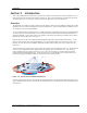

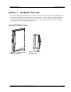
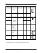
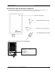

Table of Figures Trango
Trango Broadband Wireless — Access5830 User Manual Rev. H 3.0 page iv
Table of Figures
Figure 2-1: Typical Point-to-Multipoint Deployment............................................................................................................................ 1
Figure 3-1: Access5830 Series Radios (AP and SU) .......................................................................................................................... 3
Figure 3-2: FOX Series Subscriber Units ............................................................................................................................................ 3
Figure 3-3: Basic Components of an Access5830 Radio ................................................................................................................... 5
Figure 3-4: Bottom of Access Point (and 5830 Series SU) ................................................................................................................ 6
Figure 3-5: Components of FOX Series Subscriber Units.................................................................................................................. 7
Figure 3-6: Exploded View of Radio, Foam Insert, and Boot ............................................................................................................. 8
Figure 3-7: Side View of FOX Series SU............................................................................................................................................ 8
Figure 3-8: Bottom View of FOX Series SU (Boot Removed) ............................................................................................................ 9
Figure 4-1: Wiring Diagram............................................................................................................................................................... 10
Figure 4-2: Radio Management Methods ......................................................................................................................................... 11
Figure 4-3: Browser Interface Login Page........................................................................................................................................ 12
Figure 4-4: Web Browser System Information Page ........................................................................................................................ 13
Figure 4-5: Pin-outs for Serial Cable ................................................................................................................................................. 15
Figure 4-6: Terminal Settings ........................................................................................................................................................... 15
Figure 5-1: Bottom of FOX Radio with LEDs.................................................................................................................................... 21
Figure 5-2: Bottom of M5830 Radio with LEDs ................................................................................................................................ 21
Figure 7-1: M5830 Mounting Hardware Assembly ........................................................................................................................... 32
Figure 7-2: Alternative Mounting....................................................................................................................................................... 32
Figure 7-3: Articulation for M5830S-AP with Mono Pod Mount (not supplied) ................................................................................. 33
Figure 7-4: FOX Series SU Pole Mount (1” – 2” Diameter) .............................................................................................................. 34
Figure 7-5: FOX Series SU Wall Mount............................................................................................................................................ 34
Figure 7-6: FOX5800-D/Atlas Fox with Mounting Cradle for DSS Dish Antenna............................................................................. 35
Figure 7-7: FOX5800-D / AD5800-25 Reflector Dish on Pole .......................................................................................................... 35
Figure 7-8: FOX5800-D / AD5800-25 Reflector Dish on Wall .......................................................................................................... 36
Figure 7-9: Grounding Example for M5830 Series ........................................................................................................................... 36
Figure 7-10: Cat-5 Cable Strain Relief.............................................................................................................................................. 37
Figure 7-11: Grounding with Drain Wires of Shielded Twisted Pair Cat-5 Cable ............................................................................. 37
Figure 8-1 Default Channel Table (MHz)........................................................................................................................................... 40
Figure 9-1: Typical Radio System...................................................................................................................................................... 69
Figure 9-2: Attenuation of an RF signal............................................................................................................................................. 70
Figure 9-3: Radiation Pattern of Directional Antenna ....................................................................................................................... 71
Figure 9-4: Multipath Reception......................................................................................................................................................... 72
Figure 9-5: Fresnel Zone Obstruction................................................................................................................................................ 72
Figure 9-6: Fresnel Zone Radius Calculation .................................................................................................................................... 73
Table of Tables
Table 1: Access5830 Radio Description............................................................................................................................................. 4
Table 2: Reference Table of Basic AP System Information ............................................................................................................. 27
Table 3: Reference Table of Basic SU System Information ............................................................................................................. 29