
Flash Memory Card Datasheet


T
T
T
S
S
S
1
1
1
6
6
6
G
G
G
~
~
~
6
6
6
4
4
4
G
G
G
C
C
C
F
F
F
4
4
4
0
0
0
0
0
0
400X CompactFlash Card
Transcend Information Inc.
V1.0
34
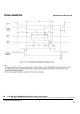
Notes:
1) All timing measurement switching points (low to high and high to low) shall be taken at 1.5 V.
2) All signal transitions for a timing parameter shall be measured at the connector specified in the measurement location
column. For example, in the case of tRFS, both STROBE and –DMARDY transitions are measured at the sender
connector.
3) The parameter tCYC shall be measured at the recipient’s connector farthest from the sender.
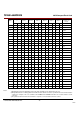
Name
UDMA Mode
0
UDMA
Mode 1
UDMA
Mode 2
UDMA
Mode 3
UDMA
Mode 4
UDMA
Mode 5
UDMA
Mode 6
Measure
location (see
Note 2)
Min
Max
Min
Max
Min
Max
Min
Max
Min
Max
Min
Max
Min
Max
t
2CYCTYP
240
160
120
90
60
40
30 Sender
t
CYC
112
73
54
39
25
16.8
13.0
Note 3
t
2CYC
230
153
115
86
57
38
29 Sender
t
DS
15.0
10.0
7.0
7.0
5.0
4.0
2.6
Recipient
t
DH
5.0
5.0
5.0
5.0
5.0
4.6
3.5
Recipient
t
DVS
70.0
48.0
31.0
20.0
6.7
4.8
4.0
Sender
t
DVH
6.2
6.2
6.2
6.2
6.2
4.8
4.0
Sender
t
CS
15.0
10.0
7.0
7.0
5.0
5.0
5.0
Device
t
CH
5.0
5.0
5.0
5.0
5.0
5.0
5.0
Device
t
CVS
70.0
48.0
31.0
20.0
6.7
10.0
10.0
Host
t
CVH
6.2
6.2
6.2
6.2
6.2
10.0
10.0
Host
t
ZFS
0
0
0
0
0
35
25 Device
t
DZFS
70.0
48.0
31.0
20.0
6.7
25
17.5
Sender
t
FS
230
200
170
130
120
90
80
Device
t
LI
0 150
0
150
0
150
0
100
0
100
0
75
0 60
Note 4
t
MLI
20
20
20
20
20
20
20 Host
t
UI
0
0
0
0
0
0
0 Host
t
AZ
10
10
10
10
10
10
10
Note 5
t
ZAH
20
20
20
20
20
20
20 Host
t
ZAD
0
0
0
0
0
0
0 Device
t
ENV
20
70
20
70
20
70
20
55
20
55
20
50
20 50
Host
t
RFS
75
70
60
60
60
50
50
Sender
t
RP
160
125
100
100
100
85
85 Recipient
t
IORDYZ
20
20
20
20
20
20
20
Device
t
ZIORDY
0
0
0
0
0
0
0 Device
t
ACK
20
20
20
20
20
20
20 Host
t
SS
50
50
50
50
50
50
50 Sender