
Flash Memory Datasheet

T
T
T
S
S
S
1
1
1
G
G
G
~
~
~
3
3
3
2
2
2
G
G
G
C
C
C
F
F
F
1
1
1
3
3
3
3
3
3
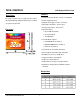
133X CompactFlash Card
Transcend Information Inc.
10
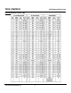
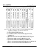
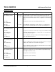
Signal Name Dir. Pin Description
-REG
(PC Card Memory Mode)
Attribute Memory Select
-REG
(PC Card I/O Mode)
I 44
This signal is used during Memory Cycles to distinguish between Common
Memory and Register (Attribute) Memory accesses. High for Common Memory,
Low for Attribute Memory.
The signal shall also be active (low) during I/O Cycles when the I/O address is on
the Bus.
-DMACK
(True IDE Mode)
This is a DMA Acknowledge signal that is asserted by the host in response to
DMARQ to initiate DMA transfers.
While DMA operations are not active, the card shall ignore the -DMACK signal,
including a floating condition.
If DMA operation is not supported by a True IDE Mode only host, this signal
should be driven high or connected to VCC by the host.
A host that does not support DMA mode and implements both PCMCIA and
True-IDE modes of operation need not alter the PCMCIA mode connections
while in True-IDE mode as long as this does not prevent proper operation all
modes.
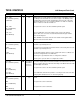
RESET
(PC Card Memory Mode)
RESET
(PC Card I/O Mode)
-RESET
(True IDE Mode)
I 41 The CompactFlash Storage Card is Reset when the RESET pin is high with the
following important exception:
The host may leave the RESET pin open or keep it continually high from the
application of power without causing a continuous Reset of the card. Under
either of these conditions, the card shall emerge from power-up having
completed an initial Reset.
The CompactFlash Storage Card is also Reset when the Soft Reset bit in the
Card Configuration Option Register is set.
This signal is the same as the PC Card Memory Mode signal.
In the True IDE Mode, this input pin is the active low hardware reset from the
host.
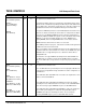
VCC
(PC Card Memory Mode)
VCC
(PC Card I/O Mode)
VCC
(True IDE Mode)
-- 13,38 +5 V, +3.3 V power.
This signal is the same for all modes.
This signal is the same for all modes.