
Flash Memory Datasheet


T
T
T
S
S
S
1
1
1
G
G
G
~
~
~
3
3
3
2
2
2
G
G
G
C
C
C
F
F
F
1
1
1
3
3
3
3
3
3
133X CompactFlash Card
Transcend Information Inc.
17
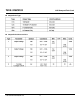
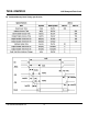
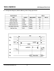
Table: Ultra DMA Termination with Pull-up or Pull down Example
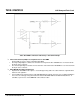
Printed Circuit Board (PCB) Trace Requirements for Ultra DMA
On any PCB for a host or device supporting Ultra DMA:
The longest D[15:00] trace shall be no more than 0.5" longer than either STROBE trace as measured from
the IC pin to the connector.
The shortest D[15:00] trace shall be no more than 0.5" shorter than either STROBE trace as measured from
the IC pin to the connector.
Ultra DMA Mode Cabling Requirement
Operation in Ultra DMA mode requires a crosstalk suppressing cable. The cable shall have a grounded line
between each signal line.
For True IDE mode operation using a cable with IDE (ATA) type 40 pin connectors it is recommended that the
host sense the cable type using the method described in the ANSI INCITS 361-2002 AT Attachment - 6
standard, to prevent use of Ultra DMA with a 40 conductor cable.