TTS S3322M M~~11G GC CFF8800 80X CompactFlash Card 1. Description 1.1 Feature The Transcend CF 80X is a High Speed Compact • RoHS compliant products Flash Card with high quality Flash Memory assembled • Compliant with CompactFlash® specification V3.0 on a printed circuit board. • Single Power Supply: 5V ± 10% / 3.
TTS S3322M M~~11G GC CFF8800 80X CompactFlash Card 1.3 Ordering Information Part Number TS32M~1GCF80 CF80 TS32M~1GCF80-P Mode True IDE mode PCMCIA mode Description Transfer mode DMA Fixed Disk Multiword DMA mode 0~4, PIO mode 0~6 Non-DMA Removable Disk N/A True IDE mode PCMCIA mode Non-DMA Fixed Disk Non-DMA Removable Disk PIO mode 0~4 N/A 1.4 CHS and Capacity Product Name Cylinder Head Sector Capacity TS32MCF80 62 16 63 29.9MB TS64MCF80 125 16 63 60.
TTS S3322M M~~11G GC CFF8800 80X CompactFlash Card 2.Product Specification 2.1 Compactflash Card Specification Transcend Transcend Information Inc. 3 V1.
TTS S3322M M~~11G GC CFF8800 80X CompactFlash Card 2.2 Block Diagram Transcend Information Inc. 4 V1.
TTS S3322M M~~11G GC CFF8800 80X CompactFlash Card 3. Electrical Interface 3.
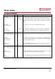
TTS S3322M M~~11G GC CFF8800 80X CompactFlash Card PC Card Memory Mode PC Card I/O Mode True IDE Mode 4 Pin Num Signal Name Pin Type In, Out Type Pin Num Signal Name Pin Type In, Out Type Pin Num Signal Name Pin Type In, Out Type 33 -VS1 O Ground 33 -VS1 O Ground 33 -VS1 O Ground 34 -IORD I I3U 34 -IORD I I3U 34 -IORD I I3Z 35 -IOWR I I3U 35 -IOWR I I3U 35 -IOWR I I3Z 36 -WE I I3U 36 -WE I I3U 36 -WE I I3U 37 READY O OT1 37 -IREQ O OT1
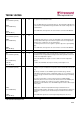
TTS S3322M M~~11G GC CFF8800 80X CompactFlash Card 3.2 Signal Description Signal Name Dir. A10 – A00 (PC Card Memory Mode) I Pin Description 8,10,11,12, These address lines along with the -REG signal are used to select the following: 14,15,16,17, The I/O port address registers within the CompactFlash Storage Card , the 18,19,20 memory mapped port address registers within the CompactFlash Storage Card, a byte in the card's information structure and its configuration control and status registers.
TTS S3322M M~~11G GC CFF8800 -CD1, -CD2 (PC Card Memory Mode) 80X CompactFlash Card O 26,25 These Card Detect pins are connected to ground on the CompactFlash Storage Card. They are used by the host to determine that the CompactFlash Storage Card is fully inserted into its socket. -CD1, -CD2 (PC Card I/O Mode) This signal is the same for all modes. -CD1, -CD2 (True IDE Mode) This signal is the same for all modes. Signal Name Dir.
TTS S3322M M~~11G GC CFF8800 D15 - D00 (PC Card Memory Mode) 80X CompactFlash Card I/O 31,30,29,28, These lines carry the Data, Commands and Status information between the host 27,49,48,47, and the controller. D00 is the LSB of the Even Byte of the Word. D08 is the LSB 6,5,4,3,2, of the Odd Byte of the Word. 23, 22, 21 D15 - D00 (PC Card I/O Mode) This signal is the same as the PC Card Memory Mode signal.
TTS S3322M M~~11G GC CFF8800 -IORD (PC Card Memory Mode) 80X CompactFlash Card I 34 This is an I/O Read strobe generated by the host. This signal gates I/O data onto the bus from the CompactFlash Storage Card when the card is configured to use the I/O interface. -IORD (PC Card I/O Mode) In True IDE Mode, this signal has the same function as in PC Card I/O Mode. -IORD (True IDE Mode ) -IOWR (PC Card Memory Mode) This signal is not used in this mode.
TTS S3322M M~~11G GC CFF8800 -REG (PC Card Memory Mode) Attribute Memory Select 80X CompactFlash Card I 44 This signal is used during Memory Cycles to distinguish between Common Memory and Register (Attribute) Memory accesses. High for Common Memory, Low for Attribute Memory. -REG (PC Card I/O Mode) The signal shall also be active (low) during I/O Cycles when the I/O address is on the Bus.
TTS S3322M M~~11G GC CFF8800 -VS1 -VS2 (PC Card Memory Mode) 80X CompactFlash Card O 33 40 Voltage Sense Signals. -VS1 is grounded on the Card and sensed by the Host so that the CompactFlash Storage Card CIS can be read at 3.3 volts and -VS2 is reserved by PCMCIA for a secondary voltage and is not connected on the Card. -VS1 -VS2 (PC Card I/O Mode) This signal is the same for all modes. -VS1 -VS2 (True IDE Mode) This signal is the same for all modes.
TTS S3322M M~~11G GC CFF8800 80X CompactFlash Card 3.3 Electrical Specification The following tables indicate all D.C. Characteristics for the CompactFlash Storage Card. Unless otherwise stated, conditions are: Vcc = 5V ±10% Vcc = 3.3V ± 5% Absolute Maximum Conditions Input Power 3.3.1 Input Leakage Current Transcend Information Inc. 13 V1.
TTS S3322M M~~11G GC CFF8800 80X CompactFlash Card 3.3.2 Input Characteristics 3.3.2.1 CompactFlash interface I/O at 5.0V Parameter Symbol Min. Max. 5.5 Supply Voltage VCC 4.5 High level output voltage VOH VCC-0.8 Low level output voltage VOL High level input voltage VIH Low level input voltage VIL Pull up resistance 2 Pull down resistance Transcend Information Inc. Unit V V 0.8 V 4.0 V Non-schmitt trigger 2.6 V Schmitt trigger 0.8 V Non-schmitt trigger 1.
TTS S3322M M~~11G GC CFF8800 80X CompactFlash Card 3.3.2.2 CompactFlash interface I/O at 3.3V Parameter Symbol Min. Max. Unit 3.465 V Supply Voltage VCC 3.135 High level output voltage VOH VCC-0.8 Low level output voltage VOL High level input voltage VIH Low level input voltage VIL Pull up resistance 2 Pull down resistance Remark V 0.8 V 2.4 V Non-schmitt trigger 1.67 V Schmitt trigger 0.6 V Non-schmitt trigger 1.07 V Schmitt trigger RPU 81.39 154.
TTS S3322M M~~11G GC CFF8800 80X CompactFlash Card 3.3.3 Output Drive Type 3.3.4 Output Drive Characteristics Transcend Information Inc. 16 V1.
TTS S3322M M~~11G GC CFF8800 80X CompactFlash Card 3.4 Signal Interface Electrical specifications shall be maintained to ensure data reliability. Item Control Signal Status Signal Card10 Host10 Signal -CE1 -CE2 -REG -IORD -IOWR -OE -WE Pull-up to VCC 500 KΩ ≧ R ≧ 50 KΩ . 1,2 RESET Pull-up to VCC 500 KΩ ≧ R ≧ 50 KΩ . 1,2,9, Pull-up to VCC 500 KΩ ≧ R≧ 50 KΩ and shall be sufficient to keep inputs inactive 1 when the pins are not connected at the host.
TTS S3322M M~~11G GC CFF8800 80X CompactFlash Card meeting all AC timing requirements: 50 pF at a DC current of 400 μ A low state and 100 μ A high state. 5) Status Signals: the socket shall present a load to the card no larger than 50 pF 10 at a DC current of 400 μ A low state and 100 μ A high state, including pull-up resistor. The card shall be able to drive at least the following load 10 while meeting all AC timing requirements: 50 pF at a DC current of 400 μ A low state and 1100 μ A high state.
TTS S3322M M~~11G GC CFF8800 80X CompactFlash Card 3.5 Attribute Memory Read Timing Figure: Attribute Memory Read Timing Diagram Transcend Information Inc. 19 V1.
TTS S3322M M~~11G GC CFF8800 80X CompactFlash Card 3.6 Configuration Register (Attribute Memory) Write Timing Figure: Configuration Register (Attribute Memory) Write Timing Diagram Transcend Information Inc. 20 V1.
TTS S3322M M~~11G GC CFF8800 80X CompactFlash Card 3.7 Common Memory Read Timing Specification Cycle Time Mode: 250 ns Max ns. Min ns. Max ns. 100 ns Min ns. Max ns. 80 ns Min ns. Ma x ns.
TTS S3322M M~~11G GC CFF8800 80X CompactFlash Card 3.8 Common Memory Write Timing Specification Cycle Time Mode: 250 ns 120 ns Max ns. Min ns. Max ns. 100 ns Min ns. Max ns. 80 ns Min ns. Item Symbol IEEE Symbol Min ns.
TTS S3322M M~~11G GC CFF8800 80X CompactFlash Card 3.9 I/O Input (Read) Timing Specification Cycle Time Mode: Item Symbol IEEE Symbol 250 ns Min ns. 120 ns Max ns. Min ns. Max ns. Min ns. Max ns. Min ns.
TTS S3322M M~~11G GC CFF8800 80X CompactFlash Card 3.10 I/O Output (Write) Timing Specification Cycle Time Mode: Item Symbol IEEE Symbol 255 ns Min ns. Max ns. 120 ns Min ns. Max ns. 100 ns Min ns. Max ns. 80 ns Min ns.
TTS S3322M M~~11G GC CFF8800 80X CompactFlash Card 3.
TTS S3322M M~~11G GC CFF8800 Transcend Information Inc. 80X CompactFlash Card 26 V1.
TTS S3322M M~~11G GC CFF8800 80X CompactFlash Card 3.12 True IDE Multiword DMA Mode Read/Write Timing Specification The timing diagram for True IDE DMA mode of operation in this section is drawn using the conventions in the ATA-4 specification. Signals are shown with their asserted state as high regardless of whether the signal is actually negative or positive true. Consequently, the -IORD, the -IOWR and the -IOCS16 signals are shown in the diagram inverted from their electrical states on the bus.
TTS S3322M M~~11G GC CFF8800 80X CompactFlash Card 4. Card Configuration The CompactFlash Storage Cards is identified by appropriate information in the Card Information Structure (CIS). The following configuration registers are used to coordinate the I/O spaces and the Interrupt level of cards that are located in the system.
TTS S3322M M~~11G GC CFF8800 80X CompactFlash Card 4.2 Attribute Memory Function Attribute memory is a space where CompactFlash Storage Card identification and configuration information are stored, and is limited to 8 bit wide accesses only at even addresses. The card configuration registers are also located here. For CompactFlash Storage Cards, the base address of the Card configuration registers is 200h.
TTS S3322M M~~11G GC CFF8800 80X CompactFlash Card 4.3 Configuration Option Register(Base + 00h in Attribute Memory) The Configuration Option Register is used to configure the cards interface, address decoding and interrupt and to issue a soft reset to the CompactFlash Storage Card. SRESET - Soft Reset: setting this bit to one (1), waiting the minimum reset width time and returning to zero (0) places the CompactFlash Storage Card in the Reset state.
TTS S3322M M~~11G GC CFF8800 80X CompactFlash Card CompactFlash Storage Card is always configured for both 8 and 16 bit I/O, so this bit is ignored. -XE: For CompactFlash cards that do not support Power Level 1, this bit has value 0 and is not writeable. Audio:This bit should always be zero for CompactFlash Storage cards. PwrDwn: this bit indicates whether the host requests the CompactFlash Storage Card to be in the power saving or active mode.
TTS S3322M M~~11G GC CFF8800 80X CompactFlash Card 4.6 Socket and Copy Register (Base + 06h in Attribute Memory) This register contains additional configuration information. This register is always written by the system before writing the card’s Configuration Index Register. This register is not required for CF Cards. If present, it is optional for a CF Card to allow setting bit D4 (Drive number) to 1.
TTS S3322M M~~11G GC CFF8800 80X CompactFlash Card port is addressed, the signal -IOIS16 is asserted by the CompactFlash Storage. Otherwise, the -IOIS16 signal is de-asserted. When a 16 bit transfer is attempted, and the -IOIS16 signal is not asserted by the CompactFlash Storage, the system shall generate a pair of 8 bit references to access the word‘s even byte and odd byte.
TTS S3322M M~~11G GC CFF8800 80X CompactFlash Card The CompactFlash Storage Card can be configured in a True IDE Mode of operation. The CompactFlash Storage Card is configured in this mode only when the -OE input signal is grounded by the host during the power off to power on cycle. Optionally, CompactFlash Storage Cards may support the following optional detection methods: 1.
TTS S3322M M~~11G GC CFF8800 80X CompactFlash Card 4.10 Host Configuration Requirements for Master/Slave or New Timing Modes The CF Advanced Timing modes include PCMCIA PC Card style I/O modes that are faster than the original 250 ns cycle time. These modes are not supported by the PCMCIA PC Card specification nor CF by cards based on revisions of the CF specification before Revision 3.0.
TTS S3322M M~~11G GC CFF8800 80X CompactFlash Card 5.1 I/O Primary and Secondary Address Configurations Table: Primary and Secondary I/O Decoding Note: 1) Register 0 is accessed with -CE1 low and -CE2 low (and A0 = Don’t Care) as a word register on the combined Odd Data Bus and Even Data Bus (D15-D0). This register may also be accessed by a pair of byte accesses to the offset 0 with -CE1 low and -CE2 high.
TTS S3322M M~~11G GC CFF8800 80X CompactFlash Card 5.2 Contiguous I/O Mapped Addressing When the system decodes a contiguous block of I/O registers to select the CompactFlash Storage Card, the registers are accessed in the block of I/O space decoded by the system as follows: Table: Contiguous I/O Decoding Notes: 1) Register 0 is accessed with -CE1 low and -CE2 low (and A0 = Don’t Care) as a word register on the combined Odd Data Bus and Even Data Bus (D15-D0).
TTS S3322M M~~11G GC CFF8800 80X CompactFlash Card 5.3 Memory Mapped Addressing When the CompactFlash Storage Card registers are accessed via memory references, the registers appear in the common memory space window: 0-2K bytes as follows: Notes: 1) Register 0 is accessed with -CE1 low and -CE2 low as a word register on the combined Odd Data Bus and Even Data Bus (D15-D0). This register may also be accessed by a pair of byte accesses to the offset 0 with -CE1 low and -CE2 high.
TTS S3322M M~~11G GC CFF8800 80X CompactFlash Card Some hosts, such as the X86 processors, must increment both the source and destination addresses when executing the memory to memory block move instruction. Some PCMCIA socket adapters also have auto incrementing address logic embedded within them. This address window allows these hosts and adapters to function efficiently.
TTS S3322M M~~11G GC CFF8800 80X CompactFlash Card Note: Because of the overlapped registers, PC Card modes access to the 1F1h, 171h or offset 1 are not defined for word (-CE2 = 0 and -CE1 = 0) operations. These accesses are treated as accesses to the Word Data Register. The duplicated registers at offsets 8, 9 and Dh have no restrictions on the operations that can be performed by the socket. Table: Data Register Access Notes: 1) -REG signal is mode dependent.
TTS S3322M M~~11G GC CFF8800 80X CompactFlash Card 5.5.3 Feature Register (Address - 1F1h[171h]; Offset 1, 0Dh Write Only) This register provides information regarding features of the CompactFlash Storage Card that the host can utilize. This register is also accessed in PC Card modes on data bits D15-D8 during a write operation to Offset 0 with -CE2 low and -CE1 high. 5.5.
TTS S3322M M~~11G GC CFF8800 80X CompactFlash Card It is Bit 27 in the Logical Block Address mode. Bit 2 (HS2): when operating in the Cylinder, Head, Sector mode, this is bit 2 of the head number. It is Bit 26 in the Logical Block Address mode. Bit 1 (HS1): when operating in the Cylinder, Head, Sector mode, this is bit 1 of the head number. It is Bit 25 in the Logical Block Address mode. Bit 0 (HS0): when operating in the Cylinder, Head, Sector mode, this is bit 0 of the head number.
TTS S3322M M~~11G GC CFF8800 80X CompactFlash Card Figure: Device Control Register Bit 7: this bit is ignored by the CompactFlash Storage Card. The host software should set this bit to 0. Bit 6: this bit is ignored by the CompactFlash Storage Card. The host software should set this bit to 0. Bit 5: this bit is ignored by the CompactFlash Storage Card. The host software should set this bit to 0. Bit 4: this bit is ignored by the CompactFlash Storage Card. The host software should set this bit to 0.
TTS S3322M M~~11G GC CFF8800 80X CompactFlash Card Bit 4 (-HS2): this bit is the negation of bit 2 in the Drive/Head register. Bit 3 (-HS1): this bit is the negation of bit 1 in the Drive/Head register. Bit 2 (-HS0): this bit is the negation of bit 0 in the Drive/Head register. Bit 1 (-nDS1): this bit is 0 when drive 1 is active and selected. Bit 0 (-nDS0): this bit is 0 when the drive 0 is active and selected. 5.
TTS S3322M M~~11G GC CFF8800 80X CompactFlash Card 5.6.1 CF-ATA Command Set CF-ATA Command Set summarizes the CF-ATA command set with the paragraphs that follow describing the individual commands and the task file for each.
TTS S3322M M~~11G GC CFF8800 80X CompactFlash Card Command Code FR SC SN CY DH LBA 28 Seek 29 Status 7Xh – – Y Y Y Y Support Set Feature EFh Y – – – Y – Support 30 Set Multiple Mode C6h – Y – – Y – Support 31 Set Sleep Mode E6h or 99h – – – – Y – Support 32 Standby E2 or 96h – – – – Y – Support 33 Standby Immediate E0 or 94h – – – – Y – Support 34 Translate Sector 87h – Y Y Y Y Y Support 35 Wear Level F5h – – – – Y – S
TTS S3322M M~~11G GC CFF8800 80X CompactFlash Card 5.6.2 Check Power Mode - 98h or E5h If the CompactFlash Storage Card is in, going to, or recovering from the sleep mode, the CompactFlash Storage Card sets BSY, sets the Sector Count Register to 00h, clears BSY and generates an interrupt. If the CompactFlash Storage Card is in Idle mode, the CompactFlash Storage Card sets BSY, sets the Sector Count Register to FFh, clears BSY and generates an interrupt.
TTS S3322M M~~11G GC CFF8800 80X CompactFlash Card 5.6.4 Erase Sector(s) - C0h This command is used to pre-erase and condition data sectors in advance of a Write without Erase or Write Multiple without Erase command. There is no data transfer associated with this command but a Write Fault error status can occur.
TTS S3322M M~~11G GC CFF8800 80X CompactFlash Card 5.6.6 Identify Device – Ech Bit -> 7 6 5 4 Command (7) C/D/H (6) 3 2 1 0 ECh X X X Drive X Cyl High (5) X Cyl Low (4) X Sec Num (3) X Sec Cnt (2) X Feature (1) X The Identify Device command enables the host to receive parameter information from the CompactFlash Storage Card. This command has the same protocol as the Read Sector(s) command.
TTS S3322M M~~11G GC CFF8800 80X CompactFlash Card Word Address Default Value Total Bytes 51 0X00h 2 PIO data transfer cycle timing mode 52 0000h 2 Obsolete 53 000Xh 2 Field Validity 54 XXXXh 2 Current numbers of cylinders 55 XXXXh 2 Current numbers of heads Data Field Type Information 56 XXXXh 2 Current sectors per track 57-58 XXXXh 4 Current capacity in sectors (LBAs)(Word 57 = LSW, Word 58 = MSW) 59 01XXh 2 Multiple sector setting 60-61 XXXXh 4 Total number of sec
TTS S3322M M~~11G GC CFF8800 80X CompactFlash Card Word 0: General Configuration This field indicates the general characteristics of the device. When Word 0 of the Identify drive information is 848Ah then the device is a CompactFlash Storage Card and complies with the CFA specification and CFA command set. It is recommended that PCMCIA modes of operation report only the 848Ah value as they are always intended as removable devices. Bits 15-0: CF Standard Configuration Value Word 0 is 848Ah.
TTS S3322M M~~11G GC CFF8800 80X CompactFlash Card Words 7-8: Number of Sectors per Card This field contains the number of sectors per CompactFlash Storage Card. This double word value is also the first invalid address in LBA translation mode. Words 10-19: Serial Number This field contains the serial number for this CompactFlash Storage Card and is right justified and padded with spaces (20h).
TTS S3322M M~~11G GC CFF8800 80X CompactFlash Card This field contains the total number of user addressable sectors for the CompactFlash Storage Card in LBA mode only. Multiword DMA transfer Bits 15 through 8 of word 63 of the Identify Device parameter information is defined as the Multiword DMA mode selected field. If this field is supported, bit 1 of word 53 shall be set to one. This field is bit significant.
TTS S3322M M~~11G GC CFF8800 80X CompactFlash Card be less than the value reported in word 68. If bit 1 of word 53 is set to one because a CompactFlash Storage Card supports a field in words 64-70 other than this field and the CompactFlash Storage Card does not support this field, the CompactFlash Storage Card shall return a value of zero in this field.
TTS S3322M M~~11G GC CFF8800 80X CompactFlash Card Bit 0 of word 85 shall be set to zero; the SMART feature set is not enabled. If bit 1 of word 85 is set to one, the Security Mode feature set has been enabled via the Security Set Password command. Bit 2 of word 85 shall be set to zero; the Removable Media feature set is not supported. Bit 3 of word 85 shall be set to one; the Power Management feature set is supported. Bit 4 of word 85 shall be set to zero; the Packet Command feature set is not enabled.
TTS S3322M M~~11G GC CFF8800 80X CompactFlash Card If set to 1, indicates that the security count has expired and Security Unlock and Security Erase Unit are command aborted until a power-on reset or hard reset. Bit 3: Freeze If set to 1, indicates that the security is Frozen. Bit 2: Lock If set to 1, indicates that the security is locked. Bit 1: Enable/Disable If set to 1, indicates that the security is enabled. If set to 0, indicates that the security is disabled.
TTS S3322M M~~11G GC CFF8800 80X CompactFlash Card mode supported by the card. Value 0 1 2 3-7 Maximum Multiword DMA timing mode supported Specified in word 63 Multiword DMA Mode 3 Multiword DMA Mode 4 Reserved Bits 8-6: Advanced True IDE PIO Mode Selected Indicates the current True IDE PIO mode selected on the card.
TTS S3322M M~~11G GC CFF8800 80X CompactFlash Card 5.6.7 Idle - 97h or E3h This command causes the CompactFlash Storage Card to set BSY, enter the Idle mode, clear BSY and generate an interrupt. If the sector count is non-zero, it is interpreted as a timer count with each count being 5 milliseconds and the automatic power down mode is enabled. If the sector count is zero, the automatic power down mode is disabled. Note that this time base (5 msec) is different from the ATA specification.
TTS S3322M M~~11G GC CFF8800 80X CompactFlash Card 5.6.10 Read Buffer - E4h The Read Buffer command enables the host to read the current contents of the CompactFlash Storage Card’s sector buffer. This command has the same protocol as the Read Sector(s) command. Bit -> 7 6 5 4 2 1 0 E4h Command (7) C/D/H (6) 3 X Drive X Cyl High (5) X Cyl Low (4) X Sec Num (3) X Sec Cnt (2) X Feature (1) X 5.6.
TTS S3322M M~~11G GC CFF8800 80X CompactFlash Card 5.6.12 Read Multiple - C4h Note: This specification requires that CompactFlash Cards support a multiple block count of 1 and permits larger values to be supported. The Read Multiple command performs similarly to the Read Sectors command. Interrupts are not generated on every sector, but on the transfer of a block, which contains the number of sectors defined by a Set Multiple command.
TTS S3322M M~~11G GC CFF8800 80X CompactFlash Card 5.6.13 Read Sector(s) - 20h or 21h This command reads from 1 to 256 sectors as specified in the Sector Count register. A sector count of 0 requests 256 sectors. The transfer begins at the sector specified in the Sector Number Register.
TTS S3322M M~~11G GC CFF8800 80X CompactFlash Card 5.6.15 Recalibrate - 1Xh This command is effectively a NOP command to the CompactFlash Storage Card and is provided for compatibility purposes. 5.6.16 Request Sense - 03h This command requests extended error information for the previous command. Table defines the valid extended error codes for the CompactFlash Storage Card Series product. The extended error code is returned to the host in the Error Register. Transcend Information Inc. 62 V1.
TTS S3322M M~~11G GC CFF8800 80X CompactFlash Card Table: Extended Error Codes 5.6.17 Seek - 7Xh This command is effectively a NOP command to the CompactFlash Storage Card although it does perform a range check of cylinder and head or LBA address and returns an error if the address is out of range. Transcend Information Inc. 63 V1.
TTS S3322M M~~11G GC CFF8800 80X CompactFlash Card 5.6.18 Set Features – EFh This command is used by the host to establish or select certain features. If any subcommand input value is not supported or is invalid, the Compact Flash Storage Card shall return command aborted. Table: Feature Supported defines all features that are supported. Table: Feature Supported Transcend Information Inc. 64 V1.
TTS S3322M M~~11G GC CFF8800 80X CompactFlash Card Features 01h and 81h are used to enable and clear 8 bit data transfer modes in True IDE Mode. If the 01h feature command is issued all data transfers shall occur on the low order D[7:0] data bus and the -IOIS16 signal shall not be asserted for data register accesses. The host shall not enable this feature for DMA transfers. Features 02h and 82h allow the host to enable or disable write cache in CompactFlash Storage Cards that implement write cache.
TTS S3322M M~~11G GC CFF8800 80X CompactFlash Card 5.6.20 Set Sleep Mode- 99h or E6h This command causes the CompactFlash Storage Card to set BSY, enter the Sleep mode, clear BSY and generate an interrupt. Recovery from sleep mode is accomplished by simply issuing another command (a reset is permitted but not required). Sleep mode is also entered when internal timers expire so the host does not need to issue this command except when it wishes to enter Sleep mode immediately.
TTS S3322M M~~11G GC CFF8800 80X CompactFlash Card 5.6.22 Standby Immediate - 94h or E0h This command causes the CompactFlash Storage Card to set BSY, enter the Sleep mode (which corresponds to the ATA “Standby” Mode), clear BSY and return the interrupt immediately. Recovery from sleep mode is accomplished by simply issuing another command (a reset is not required). 5.6.
TTS S3322M M~~11G GC CFF8800 80X CompactFlash Card 5.6.24 Wear Level - F5h For the CompactFlash Storage Cards that do not support security mode feature set, this command is effectively a NOP command and only implemented for backward compatibility. The Sector Count Register shall always be returned with a 00h indicating Wear Level is not needed. If the CompactFlash Storage Card supports security mode feature set, this command shall be handled as Security Freeze Lock. 5.6.
TTS S3322M M~~11G GC CFF8800 80X CompactFlash Card This command uses DMA mode to write from 1 to 256 sectors as specified in the Sector Count register. A sector count of 0 requests 256 sectors. The transfer begins at the sector specified in the Sector Number Register. When this command is issued the CompactFlash Storage Card sets BSY, puts all or part of the sector of data in the buffer. The Card is then permitted, although not required, to set DRQ, clear BSY.
TTS S3322M M~~11G GC CFF8800 80X CompactFlash Card Errors encountered during Write Multiple commands are posted after the attempted writes of theblock or partial block transferred. The Write command ends with the sector in error, even if it is in the middle of a block. Subsequent blocks are not transferred in the event of an error. Interrupts are generated when DRQ is set at the beginning of each block or partial block.
TTS S3322M M~~11G GC CFF8800 80X CompactFlash Card If an error occurs during a write of more than one sector, writing terminates at the sector where the error occurs. The Command Block Registers contain the cylinder, head and sector number of the sector where the error occurred. The host may then read the command block to determine what error has occurred, and on which sector. 5.6.
TTS S3322M M~~11G GC CFF8800 80X CompactFlash Card Error Posting Command Error Register BBK UNC IDNF Check Power Mode Status Register ABRT AMNF V Execute Drive Diagnostic1 Erase Sector(s) DRDY DWF DSC V V V V V V V V Format Track CORR ERR V V V V V V V V V V V V V V Identify Device V V V V V Idle V V V V V Idle Immediate V V V V V V V V Initialize Drive Parameters V Read Buffer V V V V Read DMA V V V V V V V V V V Read Multiple
TTS S3322M M~~11G GC CFF8800 80X CompactFlash Card 6.
TTS S3322M M~~11G GC CFF8800 Address Data 7 6 5 80X CompactFlash Card 4 3 2 1 0 Description of Contents CIS function 030h 1Bh CISTPL_LINK Link length is 27 bytes Link to next tuple 032h 04h TPPLV1_MAJOR PCMCIA2.0/JEIDA4.1 Major version 034h 01h TPPLV1_MINOR PCMCIA2.0/JEIDA4.
TTS S3322M M~~11G GC CFF8800 Address Data 07Eh 0Ch 7 80X CompactFlash Card 6 5 Reserved 4 3 2 1 D U V S 0 Description of Contents D=0: single drive on card CIS function TPLFE_TYPE U=1: unique serial number S=1: silicon device V=00: no VPP required 080h 0Fh R I E N P I=0: twin IOIS16# unspecified TPLFE_TYPE E=0: index bit not emulated N=0: I/O includes 0x3F7 P=F(1111):low power, sleep, standby, idle supported 082h 1Ah CISTPL_CONFIG Configuration Tuple Tuple code 084h 05h TPL_L
TTS S3322M M~~11G GC CFF8800 Address Data 098h A1h 7 80X CompactFlash Card 6 5 M MS 4 3 2 1 0 IR IO T Power Description of Contents CIS function M=1: misc info present Feature Selection MS=1: 2 byte memory length Byte TPCE_FS IR=0: no interrupt is used IO=0: no I/O space is used T=0: no timing info specified Power=1: VCC info, no VPP 09Ah 01h R DI PI AI SI HV LV NV DI: no power-down current Power Description PI:no peak current info Structure Parameter AI: no average current info Sel
TTS S3322M M~~11G GC CFF8800 Address Data 7 80X CompactFlash Card 6 5 4 3 2 1 0 Description of Contents CIS function 0B4h 1Bh CISTPL_CFTABLE_ENTRY Configuration tuple Tuple code 0B6h 0Ah CISTPL_LINK Link length is 10 bytes Link to next tuple 0B8h C1h I/O mapped, index=1 TPCE_INDX I D Configuration Index I=1: Interface byte follows D=1: Default entry 0BAh 41h W R P B Interface type W=0: wait not required TPCE_IF R=1: ready/busy active P=0: WP not used B=0: BVD1, BVD2 not used
TTS S3322M M~~11G GC CFF8800 Address Data 0C4h F0h 80X CompactFlash Card 7 6 5 4 3 2 1 0 S P M V I N S=1: interrupt sharing logic L B Description of Contents CIS function TPCE_IR P=1: pulse mode supported L=1: level mode supported M=1: masks V..N present V=0: no vendor unique IRQ B=0: no bus error IRQ I=0: no I/O check IRQ N=0: no NMI 0C6h FFh IRQ7..0 Interrupt signal may be 0C8h FFh IRQ15..
TTS S3322M M~~11G GC CFF8800 Address Data 0E2h 41h 7 80X CompactFlash Card 6 5 W R P 4 3 2 1 0 B Interface type Description of Contents W=0: wait not required CIS function TPCE_IF R=1: ready/busy active P=0: WP not used B=0: BVD1, BVD2 not used Type=1: I/O interface 0E4h 99h M MS IR IO T Power M=1: misc info present TPCE_FS MS=0: no memory space info IR=1: interrupt is used IO=1: I/O space is used T=0: no timing info specified Power=1: VCC info, no VPP 0E6h 01h R DI PI AI SI HV LV NV
TTS S3322M M~~11G GC CFF8800 Address Data 0FAh EEh 80X CompactFlash Card 7 6 5 4 S P M IRQN L 3 2 1 0 Description of Contents S=1: interrupt sharing logic CIS function TPCE_IR P=1: pulse mode supported L=1: level mode supported M=0: masks V..
TTS S3322M M~~11G GC CFF8800 Address Data 116h 99h 7 80X CompactFlash Card 6 5 4 3 2 M MS IR IO T 1 0 Power Description of Contents M=1: misc info present CIS function TPCE_FS MS=0: no memory space info IR=1: interrupt is used IO=1: I/O space is used T=0: no timing info specified Power=1: VCC info, no VPP 118h 1h R DI PI AI SI HV LV NV DI: no power-down current TPCE_PD PI:no peak current info AI: no average current info SI: no static current info HV:no max voltage info LV:no min voltage in
TTS S3322M M~~11G GC CFF8800 Address Data 12Eh 20h 80X CompactFlash Card 7 6 5 X R 4 3 2 1 P RO A T 0 Description of Contents X=0: no more misc fields CIS function TPCE_MI P=1: power-down supported RO=0:read/write media A=0: audio not supported T=0: max twins is 0 130h 1Bh CISTPL_CFTABLE_ENTRY Configuration tuple Tuple code 132h 06h CISTPL_LINK Link length is 6 bytes Link to next tuple 134h 03h I I/O mapped, index=3 TPCE_INDX 136h 01h M MS IR IO T Power Power=1: VCC info, no