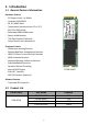
PCIe 2280 M.2 SSD MTE662T Datasheet Products Product Description TS2TMTE662T M.2 2280, PCIe Gen3x4, M-Key, 3D TLC, PE: 3K, 8CH TS1TMTE662T TS512GMTE662T Datasheet version TS256GMTE662T 1.6 No.70, Xingzhong Rd., Neihu Dist.,Taipei City 114, Taiwan, R.O.C. Tel:+886-2-2792-8000 Fax:+886-2-2792-1614 www.transcend-info.com Copyright© Transcend Information, Inc. All Rights Reserved.
Revision History Revision No. History Released Date Editor by 1.0 First version (WD BICS4) 2020/01/03 TSD 1.1 512G/1TB Write Performance Updated 512G (256Gb DDPx8) , 1TB (512Gb DDPx8) Vibration Format Updated 2020/01/14 TSD 1.2 TS1TMTE662T Picture Updated (29-5270 -> 29-5310) 2020/01/22 TSD 1.3 Add Corner Bond process information Vibration Format Updated 2020/03/03 TSD New 2TB Capacity 1.4 Add 2.6 Recommended Measurement Point Revise 5.2.
Transcend MTE662T Features Part Name Capacity TS2TMTE662T 2TB TS1TMTE662T 1TB TS512GMTE662T 512GB TS256GMTE662T 256GB FEATURES PCI Express Gen3 x 4, NVMe 3D TLC NAND Flash M.
Table of Content 1 Introduction……………………………………..………..………….…..……………….…………………………………..4 1.1General Feature Information……………………………………………………………….……………….4 1.2 Product List…………………………………………..………………………………………………..……………5 1.3 Ordering Information…………………..………………..…………………………………………….………6 2 Product Specifications…………………………………………………….……………..………………………………..7 2.1 Interface and Compliance……………………………………………………………………….…….……7 2.2 Drive Capacity…………………………………..………………………………………………………….…..…7 2.
1. Introduction 1.1 General Feature Information Hardware Feature - PCI Express Gen3 x 4, NVMe - Controller SM2262EN - 3D TLC NAND Flash - Temperature operation from 0°C to 70°C - M.
1.3 Ordering Information TSXXXGMTE662T 1 2 3 4 1 – Transcend 2 – SSD Density 3 – G: Gigabyte; T: Terabyte 4 – M.
2. Product Specifications 2.1 Interface and Compliance - Compatible with PCI Express specification Rev. 3.1 Compatible with NVM Express specification Rev. 1.3 NVM command support RoHS Compliance CE, FCC and BSMI Compliance 2.2 Drive Capacity [Table 1] User Capacity and Addressable Sectors User-Addressable Sectors 256GB 512GB 1TB 2TB 500,118,192 1,000,215,216 2,000,409,264 4,000,797,360 Byte per Sector 512 Byte 2.
2.4 Supply Voltage [Table 4] Supply Voltage Item Requirements 3.3V±5% Allowable voltage Allowable noise / ripple 100 mV p-p or less 2.5 System Power Consumption [Table 5] Power Consumption Read / Write 256GB 512GB 1TB 2TB 3.3W 3.0W 3.4W 7.0W Active Read (Max.)1) 3.3W 3.0W 3.4W 6.6W Idle 1.0W 1.0W 0.9W 0.9W Active Write (Max.) 1) Note: 1) The power consumption is measured under SSD operation at maximum performance. The value is affected by system operation performance and workload.
2.7 System Reliability [Table 7] Telcordia SR332 issue 4 MTBF Specifications Parameter 256GB 512GB MTBF 1TB 2TB 1TB 2TB 3,000,000 hours Note: 1) The calculation is based on 25°C. [Table 8] UBER Specifications Parameter 256GB 512GB UBER 10 -15 Note: 1) Uncorrectable Bit Error Rate (UBER) is a metric for the rate of occurrence of data errors, equal to the number of data errors per bits read as specified in the JESD218 document of JEDEC standard.
[Table 11] Data Retention Specifications Parameter 256GB 512GB 1TB Data Retention 2TB 1 year Note: 1) Data retention was measured by assuming that SSD reaches the maximum rated endurance at 30°C under power-off state. 2) The data retention is defined in JESD218 Requirements for standard classes of SSDs. [Table 12] Power On to Ready Parameter 256GB 512GB 1TB Setup time 2TB 9.45 s Note: 1) Tested by using Drive Master and power on to ready with proper shutdown condition.
3. Mechanical Specification The figure below illustrates the Transcend M.2 Type 2280-D2-M Solid State Drive. [Table 15] Physical Dimensions and Weight Model Height (mm) 256GB/512GB/1TB/2TB Max 3.58 11 Width (mm) 22.00±0.15 Length (mm) 80.00±0.
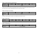
4. Pin Assignments 4.1 Pin Assignments [Table 16] Pin Assignments Pin No. Pin Name Pin No. Pin Name Pin No. Pin Name Pin No. Pin Name 01 GND 02 3.3V 39 GND 40 NC 03 GND 04 3.3V 41 PETn0 42 NC 05 PETn3 06 NC 43 PETp0 44 NC 07 PETp3 08 NC 45 GND 46 NC 09 GND 10 LED1 47 PERn0 48 NC 11 PERn3 12 3.3V 49 PERp0 50 PERST# 13 PERp3 14 3.3V 51 GND 52 CLKREQ# 15 GND 16 3.3V 53 REFCLKN 54 NC 17 PETn2 18 3.
5. Block Diagram and Function Explanations 5.1 Block Diagram 5.2 Function Explanations 5.2.1 Global Wear Leveling Function Global wear leveling ensures that every block has an even erase count. This helps to extend the life expectancy of an SSD. There are three main processes in global wear leveling: (1) Record the block erase count and save this in the wear-leveling table. (2) Find the static-block and save this in the wear-leveling pointer.
of the ECC engine, resulting in corrupted data being sent to the host. In order to prevent such occurrence, the controller monitors the error bit levels at each read operation; when it reaches the preset threshold value, the controller automatically performs data refresh to “restore” the correct charge levels in the cell. This implementation practically restores the data to its original, error-free state, and hence lengthening data life. 5.2.
The device manager may create a logical block address (LBA) range and assign different permissions for each LBA range. Only users with the correct key for a particular LBA range may perform permitted actions. Where drive locations are password-protected, only users with the correct key will be authorized entry. 5.2.8 RAID engine RAID engine technology stores data parity information in a specific area. The parity information can restore damaged data back which can enhance data reliability. 5.2.
6 Technology Term Explanations 6.1 TBW Terabytes Written (TBW) directly measures how much you can write cumulatively into the drive over its lifetime. Essentially, it just includes the multiplication conducted above in the measurement itself. For example, if your drive is rated for 365 TBW, that means you can write 365 TB into it before a replacement is required. If its warranty period is 5 years, that works out to 365 TB ÷ (5 years × 365 days/year) = 200 GB of writes per day.
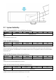
7 Installation Requirements 7.1 Card Insertion Angles insertion is allowable and preferred; the intention is to minimize the insertion/extraction force. Minimum of angle of insertion is 5° Minimum two step insertion is desirable; the intention is to minimize the insertion/extraction force.
8 Command Descriptions 8.1 Support Admin Command Register The Admin command set is the commands that are submitted to the Admin Submission Queues. The detailed specifications are described in NVM Express specification document.
8.2 SMART / Health Log Page [Table 18] SMART Data information BYTE Description Default Value Critical Warning 0 Bits Description 07:05 Reserved 04 If set to‘1’, then the volatile memory backup device has failed. This field is only valid if the controller has a volatile memory backup solution. 03 If set to‘1’, then the media has been placed in read only mode.
JAPAN 9 Contact Information E-mail: sales-jp@transcend-info.com TEL: +81-3-5820-6000 TAIWAN No.70, XingZhong Rd., NeiHu Dist., Taipei, Taiwan, R.O.C TEL +886-2-2792-8000 Fax +886-2-2793-2222 E-mail: sales-tw@transcend-info.com KOREA E-mail: sales-kr@transcend-info.com TEL: +82-2-782-8088 GERMANY E-mail: sales-de@transcend-info.com TEL: +49-40-538-907-0 Shanghai E-mail: sales-cn@transcendchina.com TEL: +86-21-6161-9388 NETHERLANDS E-mail: sales-nl@transcend-info.