Chapter 4 Installing the Encompass 4 Reader Mounting the Antenna If you are using the Encompass 4 Reader that requires an external antenna in permanent installations, the antenna should be positioned as closely as possible to the Encompass 4 Reader. Long cable runs increase system sensitivity to noise. See “Table 4 Recommended Cable Length from Transformer to the Encompass 4 Reader” on page 2–17 for maximum RF cable lengths.
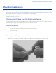
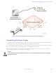
Encompass 4 Reader System Guide 2. Connect the RF cable to the antenna (see item 1 in Figure 41) 3. Short the outer metal case of the load or attenuator to Earth Ground for approximately 10 seconds (item 2 in Figure 41). In this example, the installer is using the electrical conduit for Earth Ground. Figure 41 Short Load to Earth Ground 4. Remove the load or attenuator from the RF cable and connect cable to reader.
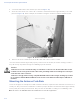
Chapter 4 Installing the Encompass 4 Reader Procedures Use the following guidelines to mount an antenna on a curb-side round pole. To mount the antenna to a curb-side pole 1. Follow the manufacturer’s directions to attach the antenna assembly to the pole approximately 8 feet (2.4 m) above the pavement surface. 2. Tighten slightly so that you can adjust the antenna left or right but not so slightly that the antenna slides down the pole. 3.
Encompass 4 Reader System Guide Note: Determine the read zone before you tighten all screws and straps permanently. Refer to the section “Marking the Read Zone” on page 4-63. After mounting the antenna, you must connect it to the Encompass 4 Reader. Follow the procedures described previously in the section “Mounting the Antenna” on page 4-49. Caution To avoid damage to the Encompass 4 Reader, you must connect the antenna before applying power to the reader.
Chapter 4 Installing the Encompass 4 Reader Figure 43 Encompass 4 Reader Installation with Overhead Antenna Connecting the Power Supply To connect the Encompass 4 Reader to a low-voltage AC power supply follow the procedures described previously in the section “Connecting the AC Power Supply” on page 4-36. To connect the Encompass 4 Reader to a low-voltage DC power supply follow the procedures described previously in the section “Connecting the DC Power Supply” on page 4-37.
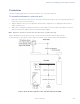
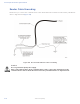
Encompass 4 Reader System Guide Reader Cable Grounding Ensure that you connect the communications cable shield drain wire to Earth Ground and the yellow/black wires to Signal Ground (Figure 44). Figure 44 Recommended Reader Cable Grounding Caution Do not ground the input power supply. After connecting the wires in the communications cable, connect the drain wire from the communications cable to Earth Ground. Connect the yellow/black wires to Signal Ground. 4-54 TransCore Proprietary.
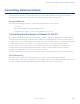
Chapter 4 Installing the Encompass 4 Reader Connecting Communications TransCore offers reader models that communicate through RS–232, RS–422, and Wiegand interface protocols. This section describes the procedures and materials required for connecting the communications to the junction box and to the sense input and sense output circuits.
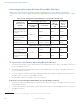
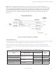
Encompass 4 Reader System Guide Connecting the Encompass 4 Reader Colored-Wire Pair Cable Table 11 shows the RS–232 colored wire (13-pair) assignments. To see the alternate wire (15-pair) assignments, refer to “Table 48 RS–232 Interface Signal Wiring for Alternate Wire 15-Pair Cable” on page C–1.
Chapter 4 Installing the Encompass 4 Reader Note: When extending the RS-232 interface, use a three-pair cable such as Belden 2919. Use a twisted pair for the Black (RxD) with ground (Black of the Black and Yellow pair), and a twisted pair for Red (TxD) with ground (Black of the Black and Yellow pair). The third pair of the three-pair cable can be used for a spare in the event either of the other two pair are damaged or fail.
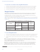
Encompass 4 Reader System Guide To connect the colored-wire cable using RS–422 interface 1. Connect the yellow wire (transmit +) from the yellow and red wire pair to the host receive (+) signal. 2. Connect the red wire (transmit –) from the yellow and red wire pair to the host receive (–) signal. 3. Connect the black wire (receive +) from the red and black wire pair to the host transmit (+) signal. 4. Connect the red wire (receive –) from the red and black wire pair to the host transmit (–) signal.
Chapter 4 Installing the Encompass 4 Reader and Black pair. Note that the black of the yellow/black is not connected. The third pair of the threepair cable can be used for a spare in the event either of the other two pair are damaged or fail. The cable shield should be tied to a single-point Earth Ground on the controller end of the cable. Refer to Figure 46. Figure 46 Wiegand Cable Extension Diagram Warning! Do not cut the RS–232 red/black wires.
Encompass 4 Reader System Guide Figure 47 Sample Circuit Connections For Encompass 4 Readers that are used with IAG protocols, the NC sense output0 common is connected to the NO sense output0 common via a jumper providing a return for sense output0 NC. Figure 48 shows this wiring. Figure 48 Sample Circuit Connections for IAG Installations 4-60 TransCore Proprietary.
Chapter 4 Installing the Encompass 4 Reader Sense Output Circuits The Encompass 4 Reader supports three sets of sense output signals. Two sets – sense output0 and sense output1 – provide NO or NC sense outputs. The third sense output set is dedicated for testing and set up of the reader. It is defined as the TAG_LOCK signal, which indicates a valid tag is in the read field. These sense outputs are dry contacts that provide NO and NC sense outputs. The relay contacts are rated at 42.
Encompass 4 Reader System Guide Table 14 Sense Input/Output Cabling 13-Pair Assignments Pair Pin R Color Signal Blue Sense Input1 Sense Input1 Black Sense Input1_ RTN Sense Input1 return; not isolated from signal ground General- purpose sense input, not used for detecting presence Switched output to control gate T Black Sense Output0_ COM Sense Output0 (tag detect), common terminal U Brown Sense Output0_NO Sense Output0 NO terminal Switched output to control gate Sense Output0_ COM Sen
Chapter 4 Installing the Encompass 4 Reader Table 14 Sense Input/Output Cabling 13-Pair Assignments Pair White/ Black Pin Z Color Black Signal Sense Output1_ COM Description Typical Function Sense Output1, common terminal Switched sense output Za Black Sync_485_P RS–485 bus positive Used to connect Encompass 4 Readers with IAG capability on a synchronization bus a White Sense Output1_NC Sense Output1 NC terminal Switched sense output Logic ground Signal ground used with RS–232 and Wiegan
Encompass 4 Reader System Guide Required Materials You need the following materials to mark the read zone: • Test tags, supplied by the TransCore dealer or distributor • Piece of windshield-type glass 0.190 to 0.230 inches (4.82 to 5.84 mm) in thickness and approximately 12 inches (30.48 cm) square for testing with a sticker tag • Audible circuit tester and 9V DC battery for circuit tester power as described in the section “Bench Testing the Encompass 4 Reader Before Installation” on page 4-39.
Chapter 4 Installing the Encompass 4 Reader Input the following commands in the order provided in “Table 10 Commands for Bench Testing” on page 4-40. Commands include those to switch to command mode, set operational mode, turn on RF, and return the reader to data mode. 5. Secure the ATA or IAG test tag to the end of the yardstick using electrical tape or hook-and-loop material or affix the test eGo Plus or eGo WST to the glass.
Encompass 4 Reader System Guide 9. Return to the center and then move to the right until the sound stops and mark the ground with chalk or tape at the location of the tag when the sound stopped. 10. Return to the center and step backward 2 feet (0.6m) and repeat steps 5 through 7. 11. Continue moving the tag in this manner, placing marks on the ground to identify the boundary of the read zone each time the sound stops. Continue moving the tag to various locations until the read zone is fully marked. 12.
Chapter 5 General Software Information Chapter 5 General Software Information This chapter provides software-related information for the Encompass® 4 Reader System. This chapter presents various software-related topics arranged in alphabetical order by subject. In addition to this chapter, see “Chapter 6 Communications Protocols” on page 6–71 and “Chapter 7 Commands” on page 7–86 for more information.
Encompass 4 Reader System Guide Command Response Conventions Like the Encompass 4 Reader commands, responses are preceded by the # character. Many Encompass 4 Reader commands respond with #Done or #Error indicating the command was or was not recognized and completed. Other commands respond with a four-character identifier followed by one or more values. Table 16 shows an example of a command/reply sequence. This example assumes that an Encompass 4 Reader with serial number SN97001P running version X.
Chapter 5 General Software Information Operating Parameters The Encompass 4 Readers maintain their operating parameters in non-volatile memory (NVRAM) so that the parameters are preserved after a power-down sequence. Caution: To save user parameter changes to NVRAM, you must send command #00 before powering down the reader. Power Fail The system maintains a power fail flag. The host transmits command #520 Display Power Fail Bit to determine if a power down has occurred.
Encompass 4 Reader System Guide Startup Upon startup, Encompass 4 Reader’s transmit a sign-on message or a boot ROM failure message. Sign-On Message If startup is successful, the sign-on message appears as follows: Model E4 Series [software version] SNYYYYYY [Copyright notice] where YYYYYY is the serial number assigned to the 4800 Reader unit being used. Serial number 000000 is the default setting and is not a valid number.
Chapter 6 Communications Protocols Chapter 6 Communications Protocols This chapter describes the communications protocols for the Encompass® 4 Reader. Introduction The Encompass 4 Reader supports the following communications protocols: • Basic • Error correcting protocol (ECP) • Data inquiry The following protocol information provides reference information relevant to developing host software.
Encompass 4 Reader System Guide Basic Protocol With basic protocol, messages sent to and from the Encompass 4 Reader and the host are transmitted without error checking. For each host transmission, the Encompass 4 Reader returns a Done or Error message to the host. When the host computer is physically close to the Encompass 4 Reader and no sources of interference exist, the basic protocol provides reliable communications.
Chapter 6 Communications Protocols Data Inquiry Protocol Data inquiry protocol is a basic protocol option that allows the host to control transmission of reader tag data. The selection of data inquiry protocol affects data mode operation. As the Encompass 4 Reader acquires tags, it buffers them but does not transmit them. Instead, the host must poll the Encompass 4 Reader for each tag by sending an ASCII CRTL-E character (hexadecimal 05).
Encompass 4 Reader System Guide When the host receives a properly framed message, it can calculate a 16-bit CRC value. The calculation is applied to the character string that immediately follows the and that ends with the character immediately preceding the first character. The transmitted CRC value can then be compared with the binary equivalent of the received characters.
Chapter 6 Communications Protocols Switch to Command Mode Request The host computer may issue command #01 Switch to Command Mode while in data mode.
Encompass 4 Reader System Guide next command, the Encompass 4 Reader will not service the new command; it will retransmit its previous message. A command/message sequence is not complete until the host updates its sequence number. Command code, a string that contains from two to four ASCII hex characters CRC value for the message [] Optional data field, an ASCII string of as many as 20 characters in length. For example, the store hardware configuration string command is #696S.
Chapter 6 Communications Protocols 4 Message sequence number KING 1302 Message data: Tag ID is shown.
Encompass 4 Reader System Guide Reader response #7Done or #7Error For some commands, the Encompass 4 Reader responds with data that relates to the command, such as T0F 0, to indicate Wiegand mode enabled for a #532 Display Wiegand Mode Status command. #7Error will be returned if host transmission is not a legal command with legal data. Timing and Synchronization The ECP is largely independent of baud rate. The timeout delays previously described are a function of baud rate.
Chapter 6 Communications Protocols before receiving an acknowledgment message, a logical NAK condition is declared, and the initiator assumes the message was received in error. In this instance, the message is retransmitted until an acknowledgment message is received. The message recipient, such as the host computer in data mode and the Encompass 4 Reader in command mode, starts a timeout counter when a character is received.
Encompass 4 Reader System Guide Receive Timeout If the Encompass 4 Reader receives a but does not receive a matching before the ECP timeout occurs, it discards the incomplete message and resets its receiver. Asynchronous Message/Command Message Collision If the Encompass 4 Reader transmits asynchronous data at the same time that the host sends a command, the Encompass 4 Reader gives priority to receiving the command.
Chapter 6 Communications Protocols To ensure this error rate is not exceeded, the host must enable parity and adhere closely to the timing specifications discussed previously in this chapter in the “Timing and Synchronization” section. CRC Calculation The CRC used by the ECP is based on a 16-bit algorithm. The algorithm, as implemented, operates on eight-bit characters, for example, seven-bit ASCII character plus one optional parity bit.
Encompass 4 Reader System Guide Example 2 shows an example of UPDCRC that does not require a lookup table.
Chapter 6 Communications Protocols 0x1080, 0x83b9, 0x02b1, 0xb5ea, 0x34e2, 0xa7db, 0x26d3, 0xd94c, 0x5844, 0xcb7d, 0x4a75, 0xfd2e, 0x7c26, 0xef1f, 0x6e17, }; 0x00a1, 0x9398, 0x1290, 0xa5cb, 0x24c3, 0xb7fa, 0x36f2, 0xc96d, 0x4865, 0xdb5c, 0x5a54, 0xed0f, 0x6c07, 0xff3e, 0x7e36, 0x30c2, 0xa3fb, 0x22f3, 0x95a8, 0x14a0, 0x8799, 0x0691, 0xf90e, 0x7806, 0xeb3f, 0x6a37, 0xdd6c, 0x5c64, 0xcf5d, 0x4e55, 0x20e3, 0xb3da, 0x32d2, 0x8589, 0x0481, 0x97b8, 0x16b0, 0xe92f, 0x6827, 0xfb1e, 0x7a16, 0xcd4d, 0x4c45, 0xdf7c
Encompass 4 Reader System Guide } for (ch = 0; ch != MAX_CHAR; ch++) printf(“0x%04x\n”, crctab[ch]); } Manually Disabling ECP for Maintenance Under certain conditions, communications between the host and Encompass 4 Reader may be lost temporarily and maintenance may be required. The reader or host is sending out a message and waiting for an acknowledgment. When the acknowledgment is not received, the message is sent again. Additional messages are also buffered.
Chapter 6 Communications Protocols Reader transmission on power-up: #0 Model …. SN Reader transmission #2 Copyright 2008 TransCore Manually enter: #0@```` #2@```` Manually enter: #101‘‘‘‘ Manually enter: Reader response: this puts reader into command mode #1Done #3610‘‘‘‘ this puts reader into basic protocol, disabling ECP Manually enter: reader response: Done Enter any other desired diagnostic or directive commands in basic protocol.
Encompass 4 Reader System Guide Chapter 7 Commands This chapter discusses the host-transmitted commands that are used to control the Encompass® 4 Reader configuration and operation. Introduction The Encompass 4 Reader is delivered from the factory with specified default settings that determine how the reader operates. Commands transmitted by the host computer can change the default settings and control additional features.
Chapter 7 Commands Note: The Encompass 4 Reader transmits ID codes to the host computer when the Encompass 4 Reader is in data mode. If the Encompass 4 Reader remains in the command mode with tags passing through the read zone, all tag IDs are not reported. Command Mode While the Encompass 4 Reader is in the command mode, the host computer sends commands to the Encompass 4 Reader that can be used to control the operation and configuration of the reader.
Encompass 4 Reader System Guide Command List Reader commands are divided into groups based on primary function. The following sections provide information about each command in command number order. Refer to “Download Mode” on page 7–87 for listings of commands in numerical and alphabetical order. In the following text, the symbols < and > represent variable message data. These symbols are not part of the message syntax.
Chapter 7 Commands Command Group 1 – Communications Port Control Group 1 commands configure the parameters used by the Encompass 4 Reader to communicate with a host computer or terminal. These commands set baud rate, stop bits, parity, and end-of-line delay. 100N Select Baud Rate See “522 Display Communications Port Parameters” on page 7–103. Command #100N selects the reader baud rate. The factory-default setting is 9600 baud. The N variable specifies the baud rate shown in Table 17.
Encompass 4 Reader System Guide Command #102N selects the reader parity setting. The factory-default setting is parity disabled. The N variable specifies parity as shown in Table 19. See “522 Display Communications Port Parameters” on page 7–103.
Chapter 7 Commands 21 Set Date Command #21 sets the date. Enter the date in the proper format: two-digit decimal entries with no spaces between characters and using forward slashes “/” as delimiters. The entry format is as follows: 21MM/DD/YY where MM represents the month (01 to 12). DD represents the day (01 to 31). YY represents the last two digits of the year (00 to 99). / is the date delimiter.
Encompass 4 Reader System Guide 30N Append Time and Date Selection Command #30N selects the option of appending the time and date to transmitted IDs, error messages, presence without tag reports, and input status change reports. The factory default setting is time and date appended (Command #302). The reader returns an Error message if its tag buffer contains data. The reset reader command #63 may be transmitted to clear the buffer; however, tag ID data will not be reported.
Chapter 7 Commands The reader transmits messages with auxiliary information appended as: % where % separates the auxiliary information and signals the host computer that auxiliary information is appended xx reader ID. Value can be set with command #60NN - auxiliary information delimiter y antenna number. Value fixed at 0 zz number of reads (00 to FF hexadecimal) of the previous tag q current status of input0 and input1 (0 to 3).
Encompass 4 Reader System Guide Command Group 4 – ID Filtering Group 4 commands set criteria for filtering (buffering or discarding) ID codes. These commands are useful for eliminating duplicate ID codes and selecting the type of tags read by the Encompass 4 Reader. 40 Transmit All ID Codes See also “530 Display RF0 Filter Status” on page 7–109. Command #40 instructs the reader to transmit all IDs without regard for uniqueness.
Chapter 7 Commands Item 3 Third-most recently acquired ID Item 4 Fourth-most recently acquired ID When the uniqueness filter is set to separation of one ID, the newly acquired ID is transmitted only if it is different from the first item. Separation of two IDs allows transmission if the new ID is different from Items 1 and 2 in the comparison register. Separation of three and four IDs transmit the new ID only if it is different from the first three and the first four items, respectively.
Encompass 4 Reader System Guide 44N Set Uniqueness Timeout See “440 Reset Uniqueness” on page 7–95. Places a time limit on the uniqueness criterion set. Refer to “410N Select Unique ID Code Criteria (Antipassback Feature)” on page 7–81. The parameter N sets the number of minutes on the timeout clock. The factory setting is two minutes (N = 1).
Chapter 7 Commands 452 Disable Tag Translation Mode (Factory Default) Command #452 disables tag translation mode. Incoming full-frame tags will be directly converted to ASCII. They will not be translated from Association of American Railroads (AAR) and American Trucking Associations (ATA) format to ASCII. Reader response: Done 453 Enable Tag Translation Mode See “534 Display Tag Translation Mode Status” on page 7–110. Command #453 enables the translation of tags in AAR and ATA formats.
Encompass 4 Reader System Guide 456 Enable eGo Plus Tag Initialization During Multi-tag Sort (Factory Default) Command #456 enables the reader to send the eGo Plus Tag initialize command as part of the multi-tag sort function. When the reader sends the eGo Plus Tag initialize command, all tags in the RF field reenter the sort process.
Chapter 7 Commands For example, 10 = 16 seconds and FF = 255 seconds. The factory default is 4601 (1 second). Uppercase or lowercase characters are allowed for NN; for example, hex digits A through F or a through f Reader response: Done For commands 480 through 489, see “570 Display Tag Protocols” on page 7–112. 480 Disable ATA Command #480 disables the reader from reading ATA protocol tags.
Encompass 4 Reader System Guide Command #489 enables the reader to read factory-programmed eATA data from eGo Plus or eGo tags. This option must be enabled to obtain Wiegand data from eGo Plus or eGo tags. 490 Disable Third Alternate Group Select (Factory Default) Command #490 is a default set in the factory to disable the third alternate group select function.
Chapter 7 Commands 492 Disable Fourth Alternate Group Select (Factory Default) Command #492 is a default set in the factory to disable the fourth alternate group select function. Reader response: Done 493 Enable Fourth Alternate Group Select Command #493 enables the fourth alternate group select function that allows the reader to distinguish tags meeting specific criteria pre-programmed into the tags.
Encompass 4 Reader System Guide 497 Enable Alternate Group Select Command #497 enables the alternate group select function that allows the reader to distinguish tags meeting specific criteria pre-programmed into the tags. Reader response: Done Command Group 5 – Reader Status Group 5 commands provide status reports on the parameters and operation of the reader. 505 Display Software Version See “695S...
Chapter 7 Commands 513 Display DSP Board Actel Version Command #513 displays DSP FPGA VER = XX.XX 520 Display Power Fail Bit Command #520 displays the value of the reader power fail bit. The power fail bit changes from 0 to 1 when power to the reader is interrupted. To reset the bit, use command #63 Reset Reader or command #65 Reset Power Fail Bit. On initial power-up, the host should transmit one of these two commands to clear the power fail bit.
Encompass 4 Reader System Guide S1 two stop bits (#1011) P0 no parity (factory default) P1 even parity (#1020) P2 odd parity (#2021) D0 00 ms end-of-line delay (fixed) (#1022) One space is required between each value. For example, if factory default settings are assigned, the reader message is MAIN B5 S0 P0 D0 indicating 9600 baud, one stop bit, no parity, and 0 ms end-of-line delay. Note: The information transmitted in response to command #522 applies to data and command mode operation only.
Chapter 7 Commands 525 Display Communications Protocol Status Command “525 Display Communications Protocol Status” on page 7–105, “610 Select Basic Communication Protocol (Factory Default)” on page 7–114, Command “614N Select Flow Control Option” on page 7–115, and Command “612NN Select Error Correcting Protocol Timeout” on page 7–114.
Encompass 4 Reader System Guide I0 Both inputs false I1 Input0 true I2 Input1 true I3 Both inputs true D0 4 ms output pulse duration D1 8 ms output pulse duration D2 12 ms output pulse duration D3 16 ms output pulse duration D4 20 ms output pulse duration D5 24 ms output pulse duration D6 32 ms output pulse duration D7 40 ms output pulse duration D8 48 ms output pulse duration D9 60 ms output pulse duration DA 76 ms output pulse duration DB 152 ms output pulse duration DC 2
Chapter 7 Commands Table 26 Open/Closed Conditions for Output Status (IAG Applications) Output0 Wire Pair Orange Jumper to Black of Brown/Black O0 Output1 Wire Pair Brown/Black White Jumper to Black of Green/Black Green/Black Closed Open Closed Open O1 Open Closed Closed Open O2 Closed Open Open Closed O3 Open Closed Open Closed Output Status Table 27 shows the input0 and input1 open/closed conditions for the input status displays.
Encompass 4 Reader System Guide T2 Uniqueness timeout of 15 seconds (#442) T3 Uniqueness timeout of 30 seconds (#443) Fxxx RF output frequency, xxx = 000 to 118 hexadecimal offset in 250 kHz from 860 MHz. If an invalid frequency value is stored (corrupted NVRAM), then xxx = “XXX” to indicate an error in the frequency setting (#647xxx or #642NN).
Chapter 7 Commands A2 (#692N) RF off on timeout or presence condition false (factory default) (#6922) T1 4 ms (#6931) T2 8 ms (#6932) T3 12 ms (#6933) T4 20 ms (#6934) T5 24 ms (#6935) T6 32 ms (#6936) T7 48 ms (#6937) T8 60 ms (#6938) T9 92 ms (#6939) TA 152 ms (#693A) TB 300 ms (#693B) TC 452 ms (#693C) TD 600 ms (#693D) TE 752 ms (#693E) TF RF timeout infinite, never expires (factory default) (#693F) I0 input inversion disabled (factory default) (#6940) I1 input invers
Encompass 4 Reader System Guide V0 Valid ID code criteria of one acquisition (#4200) V1 Valid ID code criteria of two acquisitions (#4201) V2 Valid ID code criteria of three acquisitions (#4202) V3 Valid ID code criteria of four acquisitions (#4203) For example, if factory default settings are assigned, the reader message is RF0S U0 V0 which means separation of one ID for uniqueness filtering and a valid ID code criteria of one acquisition.
Chapter 7 Commands Reader message: TT <0 to 1> where 0 tag translation mode disabled 1 tag translation mode enabled 537 Display Echo Status Command #537 displays echo mode status. In basic protocol (#610 Select Basic Protocol), the reader may be configured to enable (#6171 Enable Echo Mode) or disable (#6170 Disable Echo Mode) the echo of received commands. Refer to sections “6170 Disable Echo Mode” on page 7–115 and “6171 Enable Echo Mode (Factory Default)” on page 7–116 for more information.
Encompass 4 Reader System Guide Command #549 queries the reader for the user-programmable GSE filter data programmed in the reader using command #697. The response data is formatted similar to the data in the configuration command.
Chapter 7 Commands Table 28 Display Operating Status Mode ATA Disable #480 Enable #481 #484 #485 #482 eGo SeGo #486 IAG #488 eATA #454 Multi-tag Sort #483 #487 #489 #455 577 Report Buffered Handshakes Command #577 reports the buffered handshakes.
Encompass 4 Reader System Guide Reader response: Done 610 Select Basic Communication Protocol (Factory Default) See “525 Display Communications Protocol Status” on page 7–105. Command #610 enables the basic communications protocol. Refer to “Basic Protocol” on page 6–72 for more information. Reader response: Done 611 Select Error Correcting Protocol See “525 Display Communications Protocol Status” on page 7–105. Command #611 enables the error correcting protocol.
Chapter 7 Commands Enter CTRL_E to get data. Caution Ensure that the ECP timeout is sufficient for a given baud rate. See “Timing and Synchronization” on page 6–78. 613 Enable Data Inquiry Protocol Command #613 enables the data inquiry protocol. Refer to “410N Select Unique ID Code Criteria (Antipassback Feature)” on page 7–81, “410N Select Unique ID Code Criteria (Anti-passback Feature)” on page 7–94 for more information.
Encompass 4 Reader System Guide the command, but only transmits its response. The reader never echoes while in ECP or download mode operation. Reader response: Done 6171 Enable Echo Mode (Factory Default) Command #6171 enables the reader to echo received host commands. Command #6170 disables echo mode. Reader response: Done 620N Set Output Control See “526 Display I/O Status” on page 7–105 and “621 Select Predefined Output Control (Factory Default)” on page 7–116.
Chapter 7 Commands Reader response: Done 63 Reset Reader See “526 Display I/O Status” on page 7–105, “620N Set Output Control” on page 7–116, and “67N Set Output Pulse Duration” on page 7–125. Command #63 resets the power fail bit, stores non-volatile memory (NVM) parameters, clears all buffers, resets tag uniqueness, turns off both output lines, transmits the sign-on message, and returns to the data mode. Note: This command does not reset any other configuration parameters.