
User's Manual


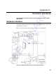


Table Of Contents
- Health Limits
- Contents
- Before You Begin
- Developing the Installation Site Plan
- Installing and Configuring the MPI 6000
- Lane Tuning Guidelines
- Optimizing MPI 6000 Reader System Performance
- General Software Information
- Configuration Commands and Responses
- Configuring the MPI 6000
- Required Commands to Set Up MPI 6000 Reader
- System Interface Command Group Commands
- System Identify
- Set Communications Baud Rate
- Get Communications Baud Rate
- Set Time and Date
- Get Time and Date
- Firmware Download
- Reset Reader
- Get Stored Tag Response Message
- Get Number of Stored Tag Response Messages
- Delete All Stored Tag Response Messages
- Get System Startup Status
- Get Lane Controller Interface Status
- Get System Interface Status
- Get DigBrd Hdwr Remote Inventory
- Get DigBrd CPU Boot Fmwr Remote Inventory
- Get DigBrd CPU Appl Fmwr Remote Inventory
- Get DigBrd FPGA UDP/IP Core Fmwr Remote Inventory
- Get UDP/IP Core Lane Controller Parameters
- Set UDP/IP Core IP Address
- Get UDP/IP Core IP Address
- Get UDP/IP Core Port Number
- Configuring the MPI 6000
- Tag Command Processing
- System Diagnostics and Preventive Maintenance
- Acronyms and Glossary
- Block Diagrams
- System Technical Specifications
- Hardware Interfaces
MPI 6000 Multi-Protocol Reader System Guide
D-4
Communications
The MPI 6000 communicates with a host via Ethernet or serial communicaitons.
Ethernet
The connector is an RJ-45 jack. This interface is 10-base T. Table D-1 lists the pin-
outs.
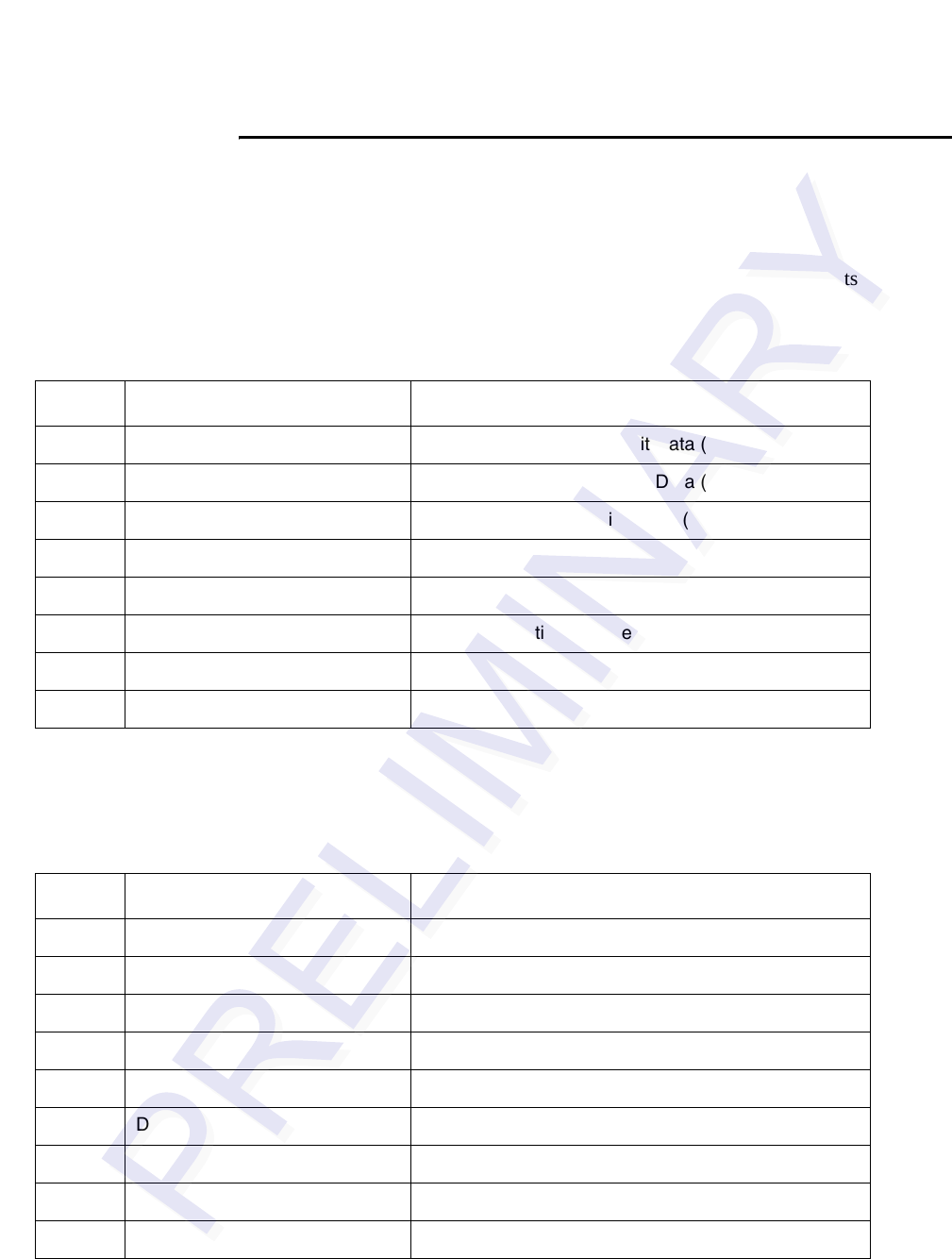
RS-232 Connectors
Table D-1 Ethernet Connector Pin-outs
Pin Signal Description
1 TPTX+ Output Differential Transmit Data (+)
2 TPTX- Output Differential Transmit Data (-)
3 TPRX+ Input Differential Receive Data (+)
4 Not connected N/A
5 Not connected N/A
6 TPRX- Input Differential Receive Data (-)
7 Not connected N/A
Not connected N/A
Table D-2 RS-232A Communications Connector Parameters
Pin Signal Description
1 RSD Received line signal detect (not connected)
2 RXD Receive Data
3 TXD Transmit Data
4 DTR Data Terminal Ready (not connected)
5 GND Ground
6 DSR Data Set Ready (not connected)
7 RTS Request to Send
8 CTS Clear to Send
9 RI Ring indicator (not connected)