
User's Manual

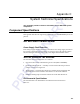


Table Of Contents
- Health Limits
- Contents
- Before You Begin
- Developing the Installation Site Plan
- Installing and Configuring the MPI 6000
- Lane Tuning Guidelines
- Optimizing MPI 6000 Reader System Performance
- General Software Information
- Configuration Commands and Responses
- Configuring the MPI 6000
- Required Commands to Set Up MPI 6000 Reader
- System Interface Command Group Commands
- System Identify
- Set Communications Baud Rate
- Get Communications Baud Rate
- Set Time and Date
- Get Time and Date
- Firmware Download
- Reset Reader
- Get Stored Tag Response Message
- Get Number of Stored Tag Response Messages
- Delete All Stored Tag Response Messages
- Get System Startup Status
- Get Lane Controller Interface Status
- Get System Interface Status
- Get DigBrd Hdwr Remote Inventory
- Get DigBrd CPU Boot Fmwr Remote Inventory
- Get DigBrd CPU Appl Fmwr Remote Inventory
- Get DigBrd FPGA UDP/IP Core Fmwr Remote Inventory
- Get UDP/IP Core Lane Controller Parameters
- Set UDP/IP Core IP Address
- Get UDP/IP Core IP Address
- Get UDP/IP Core Port Number
- Configuring the MPI 6000
- Tag Command Processing
- System Diagnostics and Preventive Maintenance
- Acronyms and Glossary
- Block Diagrams
- System Technical Specifications
- Hardware Interfaces
MPI 6000 Multi-Protocol Reader System Guide
D-6
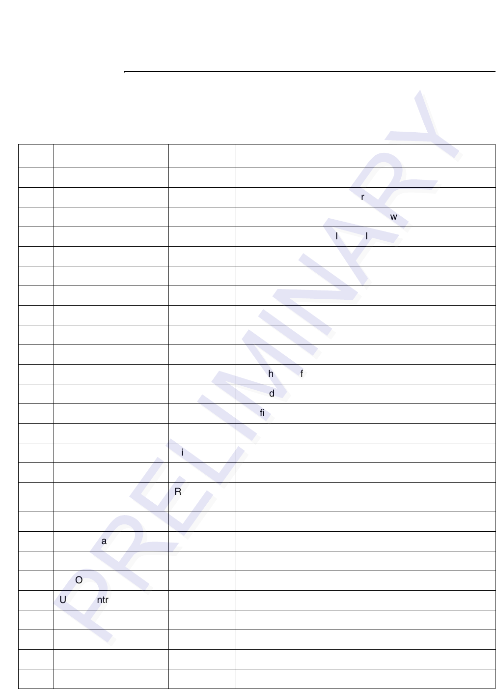
Hardware Diagnostic Port
Table D-5 MPI 6000 Hardware Diagnostic Port Parameters
Pin Signal Source Description
1 I RF I Channel from RF receiver
2 Q RF Q Channel from RF receiver
3 RSSI RF RSSI Detector Output, high for I low for Q.
4 RANGE_ADJ_CNTL RF Range Adjust_Control Signal
5 +3.3V Digital +3.3V
6 Spare RF
7 GND Ground
8 Spare RF
9 Spare RF
10 IAG_New_Sig_Det RF IAG New Signal Detection Line
11 IAG RF IAG Channel from RF receiver
12 GND Ground
13 Config Type 0 Digital Configuration Selection bit 1
14 Config Type 1 Digital Configuration Selection bit 2
15 Config Type 2 Digital Configuration Selection bit 3
16 Config Type 3 Digital Configuration Selection bit 4
17 Tag Ty p e A ck RF Acks the tag type inputs and indicates that the DL & DOM
DACS are settled.
18 Ready to Tx RF Ready to Transmit
19 Config Load Digital Signal to RF to load new config.
20 MOD Digital RF Modulation Signal
21 RF ON/OFF Digital RF On Off Control
22 UL/DL Cntrl Digital Controls whether active source is Uplink or Downlink
23 TDM Digital TDM Sync Pulse
24 GPS 1pps Digital 1 pulse per second signal for Frequency stabilization
25 Error (txcvr fault) RF RF Error Indicator active low
26 Power Supply Fault Digital Fault Signal from the Power Supply Board