
User's Manual
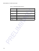

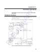


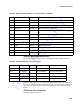
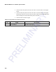
Table Of Contents
- Health Limits
- Contents
- Before You Begin
- Developing the Installation Site Plan
- Installing and Configuring the MPI 6000
- Lane Tuning Guidelines
- Optimizing MPI 6000 Reader System Performance
- General Software Information
- Configuration Commands and Responses
- Configuring the MPI 6000
- Required Commands to Set Up MPI 6000 Reader
- System Interface Command Group Commands
- System Identify
- Set Communications Baud Rate
- Get Communications Baud Rate
- Set Time and Date
- Get Time and Date
- Firmware Download
- Reset Reader
- Get Stored Tag Response Message
- Get Number of Stored Tag Response Messages
- Delete All Stored Tag Response Messages
- Get System Startup Status
- Get Lane Controller Interface Status
- Get System Interface Status
- Get DigBrd Hdwr Remote Inventory
- Get DigBrd CPU Boot Fmwr Remote Inventory
- Get DigBrd CPU Appl Fmwr Remote Inventory
- Get DigBrd FPGA UDP/IP Core Fmwr Remote Inventory
- Get UDP/IP Core Lane Controller Parameters
- Set UDP/IP Core IP Address
- Get UDP/IP Core IP Address
- Get UDP/IP Core Port Number
- Configuring the MPI 6000
- Tag Command Processing
- System Diagnostics and Preventive Maintenance
- Acronyms and Glossary
- Block Diagrams
- System Technical Specifications
- Hardware Interfaces
Hardware Interfaces
D-7
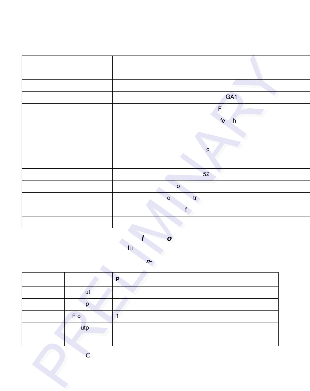
Antenna Multiplexer Connectors
The antenna multiplexer is used to drive multiple antennas in multiple AVI lanes.
Connector D21 is the same as connector B11 on the digital board. Connector D28 is
the same as connector B11 on the digital board. This connector is used to connect the
data cables from the MPI 6000 to the antenna multiplexer and the RF System Test
boards.
RF System Test Connectors
The RF system test checks the ...
27 GND Ground
28 Tx Serial Comm Digital Transmit Serial Signal
29 Rx Serial Comm RF Receive Serial Signal
30 GoodTagRead Digital Active High Pulse from FPGA1
31 CRC Failed Digital Active High Pulse from FPGA1
32 ActivatePort Digital Enable the Test Port Buffer when the Connector plugged
in
33 GND Ground
34 SW1 Digital GPIO from MPC852
35 SW2 Digital GPIO from MPC852
36 SW3 Digital GPIO from MPC852
37 SW4 Digital GPIO from MPC852
38 DecoderOutput Digital Decoder Bit Stream from FPGA1
39 PLL Clock (decoder) Digital PLL Clock from FPGA1
40 GND Digital Ground
Table D-5 MPI 6000 Hardware Diagnostic Port Parameters (continued)
Table D-6 Antenna Multiplexer Connector Pin-outs
Connector Designator
Pin Signal Description
D16 RF input1 1 RF Input/Output RF input/output signal
D17 RF output 1 1 RF Input/Output RF input/output signal
D18 RF output 2 1 RF Input/Output RF input/output signal
D19 RF output 3 1 RF Input/Output RF input/output signal
D20 RF output 4 1 RF Input/Output RF input/output signal