
User's Manual


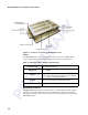
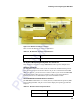


Table Of Contents
- Health Limits
- Contents
- Before You Begin
- Developing the Installation Site Plan
- Installing and Configuring the MPI 6000
- Lane Tuning Guidelines
- Optimizing MPI 6000 Reader System Performance
- General Software Information
- Configuration Commands and Responses
- Configuring the MPI 6000
- Required Commands to Set Up MPI 6000 Reader
- System Interface Command Group Commands
- System Identify
- Set Communications Baud Rate
- Get Communications Baud Rate
- Set Time and Date
- Get Time and Date
- Firmware Download
- Reset Reader
- Get Stored Tag Response Message
- Get Number of Stored Tag Response Messages
- Delete All Stored Tag Response Messages
- Get System Startup Status
- Get Lane Controller Interface Status
- Get System Interface Status
- Get DigBrd Hdwr Remote Inventory
- Get DigBrd CPU Boot Fmwr Remote Inventory
- Get DigBrd CPU Appl Fmwr Remote Inventory
- Get DigBrd FPGA UDP/IP Core Fmwr Remote Inventory
- Get UDP/IP Core Lane Controller Parameters
- Set UDP/IP Core IP Address
- Get UDP/IP Core IP Address
- Get UDP/IP Core Port Number
- Configuring the MPI 6000
- Tag Command Processing
- System Diagnostics and Preventive Maintenance
- Acronyms and Glossary
- Block Diagrams
- System Technical Specifications
- Hardware Interfaces
Installing and Configuring the MPI 6000
3-5
Figure 3-2 Antenna Connector Location
Table 3-2 lists the RF antenna connector parameters.
RF Antenna Multiplexing/RF System Test Connector
This connector is used when a single MPI 6000 is used to operate multiple lanes.
Ethernet Connector
The MPI 6000 communicates with a host via an Ethernet communications protocol.
This connection requires an RJ
–45 connector. If you use a switch between the MPI
6000 and a host PC, you do not need a crossover cable. If you connect the MPI 6000
directly to a host PC then you need a crossover cable. If you set the host PC to
Dynamic, TransCore recommends that you set the IP address to Static.
RS–232A Serial Communications Connector
The MPI 6000 communicates via a serial, RS–232, communications protocol (Table
3-3). The diagnostic RS–232 port can be used to display the operating system boot
sequence.
Antenna Connector
Table 3-2 RF Antenna Connector Specifications
Connector Type
SMA Female
Output Power
Up to 2 watts
Table 3-3 RS-232 Connector Specifications
Connector Type
9 pin D-sub male
Protocol
RS-232