
User's Manual


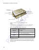


Table Of Contents
- Health Limits
- Contents
- Before You Begin
- Developing the Installation Site Plan
- Installing and Configuring the MPI 6000
- Lane Tuning Guidelines
- Optimizing MPI 6000 Reader System Performance
- General Software Information
- Configuration Commands and Responses
- Configuring the MPI 6000
- Required Commands to Set Up MPI 6000 Reader
- System Interface Command Group Commands
- System Identify
- Set Communications Baud Rate
- Get Communications Baud Rate
- Set Time and Date
- Get Time and Date
- Firmware Download
- Reset Reader
- Get Stored Tag Response Message
- Get Number of Stored Tag Response Messages
- Delete All Stored Tag Response Messages
- Get System Startup Status
- Get Lane Controller Interface Status
- Get System Interface Status
- Get DigBrd Hdwr Remote Inventory
- Get DigBrd CPU Boot Fmwr Remote Inventory
- Get DigBrd CPU Appl Fmwr Remote Inventory
- Get DigBrd FPGA UDP/IP Core Fmwr Remote Inventory
- Get UDP/IP Core Lane Controller Parameters
- Set UDP/IP Core IP Address
- Get UDP/IP Core IP Address
- Get UDP/IP Core Port Number
- Configuring the MPI 6000
- Tag Command Processing
- System Diagnostics and Preventive Maintenance
- Acronyms and Glossary
- Block Diagrams
- System Technical Specifications
- Hardware Interfaces

Installing and Configuring the MPI 6000
3-7
2. Run setup.exe and follow the commands to install the Host. The setup procedure
installs an icon named MPI 6000 Host on your computer desktop.
The following sections tell you how to use the MPI 6000 Host software.
Connecting to the MPI 6000 Reader with the Host Software
1. Double-click on the MPI 6000 Host icon.
2. Select UDP on the main screen.
3. In the UDP Command Link Config field, enter the IP address of the reader.
Write the IP address near the Ethernet connector on the MPI 6000 enclosure for
future reference.
4. Select Establish Command Link.
5. Select E.xit.
Configuring the MPI 6000 Reader Operating Frequency
1. Select the Configuration tab.
2. Select the Transceiver Configuration sub-tab.
3. Set the frequencies to desire values. Nominal values are 918.75 for downlink and
903 for uplink. Values must be between 902.25 and 903.75 or between 910 and
918.75 for the downlink. Values must be between 912.75 and 918.75 for the
uplink.
Operating the MPI 6000 Reader
1. Select Tags > FDOT.
2. Enter hex data into the IT2200 Write Data and SeGo Page Data fields. Use 32
hex characters for IT2200 (Allegro) and 16 hex characters for SeGo. This is the
data that is going to be written to the tag.
3. Select Read or Write in the SeGo Sequence Field. This sets the Read or Write
parameters for both IT2200 and SeGo tags.
4. Press Start to begin tag processing.
5. Tag responses should appear in the IT2200 and SeGo fields.
6. To stop the display or the response count, select the check boxes.
7. Press Stop to end tag processing.
8. Press Exit to close the FDOT page.
MPI 6000 Readers have been preconfigured for most needed operations. Parameters
such as attenuation, step-lock settings, and tag command sequences are set when the
reader powers up.