
User's Manual


Table Of Contents
- Health Limits
- Contents
- Before You Begin
- Developing the Installation Site Plan
- Installing and Configuring the MPI 6000
- Lane Tuning Guidelines
- Optimizing MPI 6000 Reader System Performance
- General Software Information
- Configuration Commands and Responses
- Configuring the MPI 6000
- Required Commands to Set Up MPI 6000 Reader
- System Interface Command Group Commands
- System Identify
- Set Communications Baud Rate
- Get Communications Baud Rate
- Set Time and Date
- Get Time and Date
- Firmware Download
- Reset Reader
- Get Stored Tag Response Message
- Get Number of Stored Tag Response Messages
- Delete All Stored Tag Response Messages
- Get System Startup Status
- Get Lane Controller Interface Status
- Get System Interface Status
- Get DigBrd Hdwr Remote Inventory
- Get DigBrd CPU Boot Fmwr Remote Inventory
- Get DigBrd CPU Appl Fmwr Remote Inventory
- Get DigBrd FPGA UDP/IP Core Fmwr Remote Inventory
- Get UDP/IP Core Lane Controller Parameters
- Set UDP/IP Core IP Address
- Get UDP/IP Core IP Address
- Get UDP/IP Core Port Number
- Configuring the MPI 6000
- Tag Command Processing
- System Diagnostics and Preventive Maintenance
- Acronyms and Glossary
- Block Diagrams
- System Technical Specifications
- Hardware Interfaces
MPI 6000 Multi-Protocol Reader System Guide
4-8
ATA Tag Protocol
TBD
IAG Tag Protocol
TBD
Frequency Considerations — Multiple Protocols
TBD
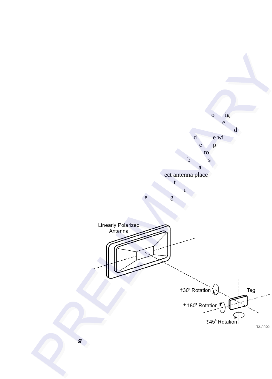
Antenna-Tag Orientation
Antennas need to be oriented to match the tag orientation (Figure 4-2). Antennas also
need to match the tag placement and vice versa. For example, if the tag is placed in the
center of the windshield, the antennas should be placed overhead, centered, or nearly
centered in the lane. If the tag is placed to the side of the windshield, the antennas
should be placed overhead to the side matching the tag placement, or a side-mounted
antenna should be used. There are some exceptions to this, and in the overall system
planning, any variation from this rule should be discussed with TransCore at the earli
-
est possible time to minimize additional costs for altering the lane design, especially
after construction has started. Incorrect antenna placement may render the system’s
performance unacceptable and result in the eventual and expensive refitting of
antenna and communication hardware.
Figure 4-3 shows interior tag mounting loca-
tions, and Figure 4-4 shows exterior tag mounting locations.
Figure 4-2 Tag Orientation with Linearly Polarized Antenna