
User's Manual


Table Of Contents
- Health Limits
- Contents
- Before You Begin
- Developing the Installation Site Plan
- Installing and Configuring the MPI 6000
- Lane Tuning Guidelines
- Optimizing MPI 6000 Reader System Performance
- General Software Information
- Configuration Commands and Responses
- Configuring the MPI 6000
- Required Commands to Set Up MPI 6000 Reader
- System Interface Command Group Commands
- System Identify
- Set Communications Baud Rate
- Get Communications Baud Rate
- Set Time and Date
- Get Time and Date
- Firmware Download
- Reset Reader
- Get Stored Tag Response Message
- Get Number of Stored Tag Response Messages
- Delete All Stored Tag Response Messages
- Get System Startup Status
- Get Lane Controller Interface Status
- Get System Interface Status
- Get DigBrd Hdwr Remote Inventory
- Get DigBrd CPU Boot Fmwr Remote Inventory
- Get DigBrd CPU Appl Fmwr Remote Inventory
- Get DigBrd FPGA UDP/IP Core Fmwr Remote Inventory
- Get UDP/IP Core Lane Controller Parameters
- Set UDP/IP Core IP Address
- Get UDP/IP Core IP Address
- Get UDP/IP Core Port Number
- Configuring the MPI 6000
- Tag Command Processing
- System Diagnostics and Preventive Maintenance
- Acronyms and Glossary
- Block Diagrams
- System Technical Specifications
- Hardware Interfaces
MPI 6000 Multi-Protocol Reader System Guide
4-10
ing license plate tags.
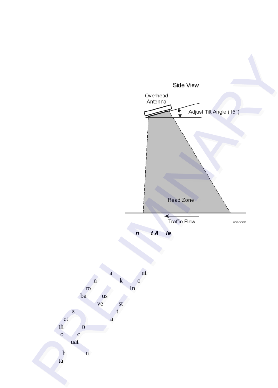
Note: TransCore does not recommend placing the antenna uptilt angles at less than five degrees.
Figure 4-5 Overhead Antenna Tilt Angle
Antenna Positioning Within the Lane
In lanes where the antennas are mounted side by side, TransCore recommends that you install the
transmit antenna toward the driver side of the traffic lane and the receive antenna toward the pas
-
senger side of the traffic lane. Antenna position in the lane also impacts lane performance.
Antenna mounting brackets should be designed so that you can adjust the antennas from front to
back and from side to side. In lanes that have no vehicle framing, such as some express lanes, the
front-to-back adjustment is not critical and can be minimized or eliminated. But, in these lanes it is
still valid to have at least ±2 feet (±0.61 m) of side adjustment. Side adjustment may be critical in
places where vehicles tend to travel to one side or another, such as in lanes that are wider than 12
feet (3.65 m). You can move the pair of antennas from side to side so that the centerline between
the antenna pair is located over the area of the lane where the majority of traffic travels. RF reflec
-
tors, such as toll booths and Jersey barriers, may require you to make side adjustments to achieve
adequate coverage to one side or the other.
The portion of the footprint with the highest RF margin has the highest probability of a successful
tag transaction. This portion of the footprint is the area directly under the antenna and extending
forward (upstream) a number of feet. If the length of the footprint is not an issue, such as the situa
-
tion in some lower speed mixed-use lanes, but the point of first read is critical, it may be advisable
to use a low antenna angle. Next, adjust the antenna position so that the first read occurs at the
desired point. Adjust the antenna position instead of fixing the antenna position and adjusting the
first read point by manipulating the antenna uptilt angle or the RF power. This adjustment may