User's Manual
Table Of Contents
- Health Limits
- Contents
- Before You Begin
- Developing the Installation Site Plan
- Installing and Configuring the MPI 6000
- Lane Tuning Guidelines
- Optimizing MPI 6000 Reader System Performance
- General Software Information
- Configuration Commands and Responses
- Configuring the MPI 6000
- Required Commands to Set Up MPI 6000 Reader
- System Interface Command Group Commands
- System Identify
- Set Communications Baud Rate
- Get Communications Baud Rate
- Set Time and Date
- Get Time and Date
- Firmware Download
- Reset Reader
- Get Stored Tag Response Message
- Get Number of Stored Tag Response Messages
- Delete All Stored Tag Response Messages
- Get System Startup Status
- Get Lane Controller Interface Status
- Get System Interface Status
- Get DigBrd Hdwr Remote Inventory
- Get DigBrd CPU Boot Fmwr Remote Inventory
- Get DigBrd CPU Appl Fmwr Remote Inventory
- Get DigBrd FPGA UDP/IP Core Fmwr Remote Inventory
- Get UDP/IP Core Lane Controller Parameters
- Set UDP/IP Core IP Address
- Get UDP/IP Core IP Address
- Get UDP/IP Core Port Number
- Configuring the MPI 6000
- Tag Command Processing
- System Diagnostics and Preventive Maintenance
- Acronyms and Glossary
- Block Diagrams
- System Technical Specifications
- Hardware Interfaces

Optimizing MPI 6000 Reader System Performance
5-5
Diagnosing Cross-Lane Interference
To diagnose this type of interference, first set the RF power in all lanes to a moderate
setting of 6 to 9 decibels (dB) for both downlink and uplink antennas. Next, tune a sin
-
gle lane. When tuning a lane be sure to use a tag and vehicle that have been used con-
sistently at your site.
Once the lane has been tuned and you determine that it is working satisfactorily, per-
form lane tuning procedures in the adjacent lane. Continue for each lane in the toll
plaza.
If each adjacent lane tuning causes the previously tuned lane to start performing
poorly (i.e., spotty read zone or areas of no reads), cross-lane interference is indicated.
Remedying Cross-Lane Interference
Several methods exist to remedy cross-lane interference. These remedies are accom-
plished by software or hardware changes, or a combination of both. A remedy at one
site may not be appropriate at another site, so iterative methods of correcting this
interference are necessary.
Frequency Separation
Review the toll plaza frequency plan that was developed during the eGo 4110A
Reader System installation phase. There are two frequencies for each reader: down
-
link and uplink. For the eGo 4110A Reader System, all readers share the same down-
link frequency, which is generally set to 918.75 MHz. Uplink frequencies should
alternate between 903.00 MHz and 910.00 MHz in adjacent lanes. For example, a
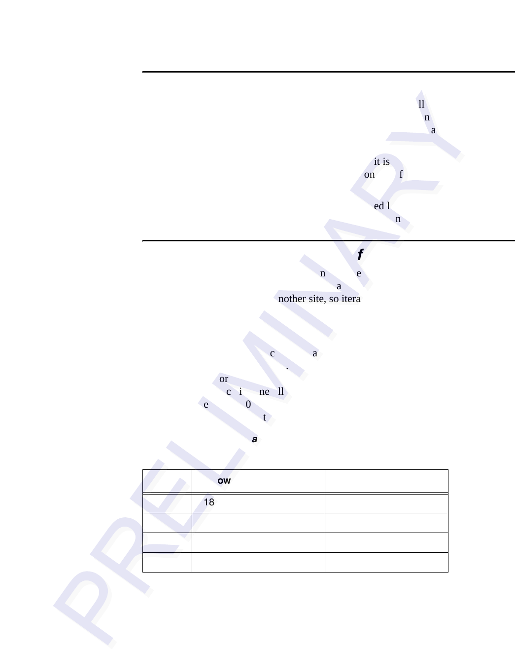
four-lane plaza would have the frequencies shown in
Table 5-1.
RF Power
A good rule of thumb when configuring a toll plaza is to set the RF attenuation at a
lower output and increase the RF power level as needed for optimal system operation.
This practice may provide you with RF attenuation settings at which your reader sys
-
tem can operate with minimal adjustment for cross-lane interference.
Table 5-1 Frequency Plan for Four-Lane Toll Plaza Using IT2200-series or Title
21 Tag Protocol
Lane Downlink Frequency Uplink Frequency
1 918.75 MHz 903.00 MHz
2 918.75 MHz 910.00 MHz
3 918.75 MHz 903.00 MHz
4 918.75 MHz 910.00 MHz


