
User's Manual


Table Of Contents
- Health Limits
- Contents
- Before You Begin
- Developing the Installation Site Plan
- Installing and Configuring the MPI 6000
- Lane Tuning Guidelines
- Optimizing MPI 6000 Reader System Performance
- General Software Information
- Configuration Commands and Responses
- Configuring the MPI 6000
- Required Commands to Set Up MPI 6000 Reader
- System Interface Command Group Commands
- System Identify
- Set Communications Baud Rate
- Get Communications Baud Rate
- Set Time and Date
- Get Time and Date
- Firmware Download
- Reset Reader
- Get Stored Tag Response Message
- Get Number of Stored Tag Response Messages
- Delete All Stored Tag Response Messages
- Get System Startup Status
- Get Lane Controller Interface Status
- Get System Interface Status
- Get DigBrd Hdwr Remote Inventory
- Get DigBrd CPU Boot Fmwr Remote Inventory
- Get DigBrd CPU Appl Fmwr Remote Inventory
- Get DigBrd FPGA UDP/IP Core Fmwr Remote Inventory
- Get UDP/IP Core Lane Controller Parameters
- Set UDP/IP Core IP Address
- Get UDP/IP Core IP Address
- Get UDP/IP Core Port Number
- Configuring the MPI 6000
- Tag Command Processing
- System Diagnostics and Preventive Maintenance
- Acronyms and Glossary
- Block Diagrams
- System Technical Specifications
- Hardware Interfaces
MPI 6000 Multi-Protocol Reader System Guide
5-6
Time-Division Multiplexing
In situations where cross-lane interference can occur in an installation, and frequency
management is not sufficient to solve the problem, you may need to use time-division
multiplexing (TDM). By using the TDM function in readers, individual readers oper
-
ate only during interleaved time periods.
The TDM interconnect is provided via a differential RS–485 interface to a DB9 con-
nector that is located on the reader card’s expansion board connector in slot 2. This
connection provides a synchronization interface between readers where RF interfer
-
ence between readers is reduced by multiplexing the RF reader transmission to inde-
pendent time slots. Allowing each reader or group of readers to operate at an allotted
time eliminates interference from readers in adjacent lanes.
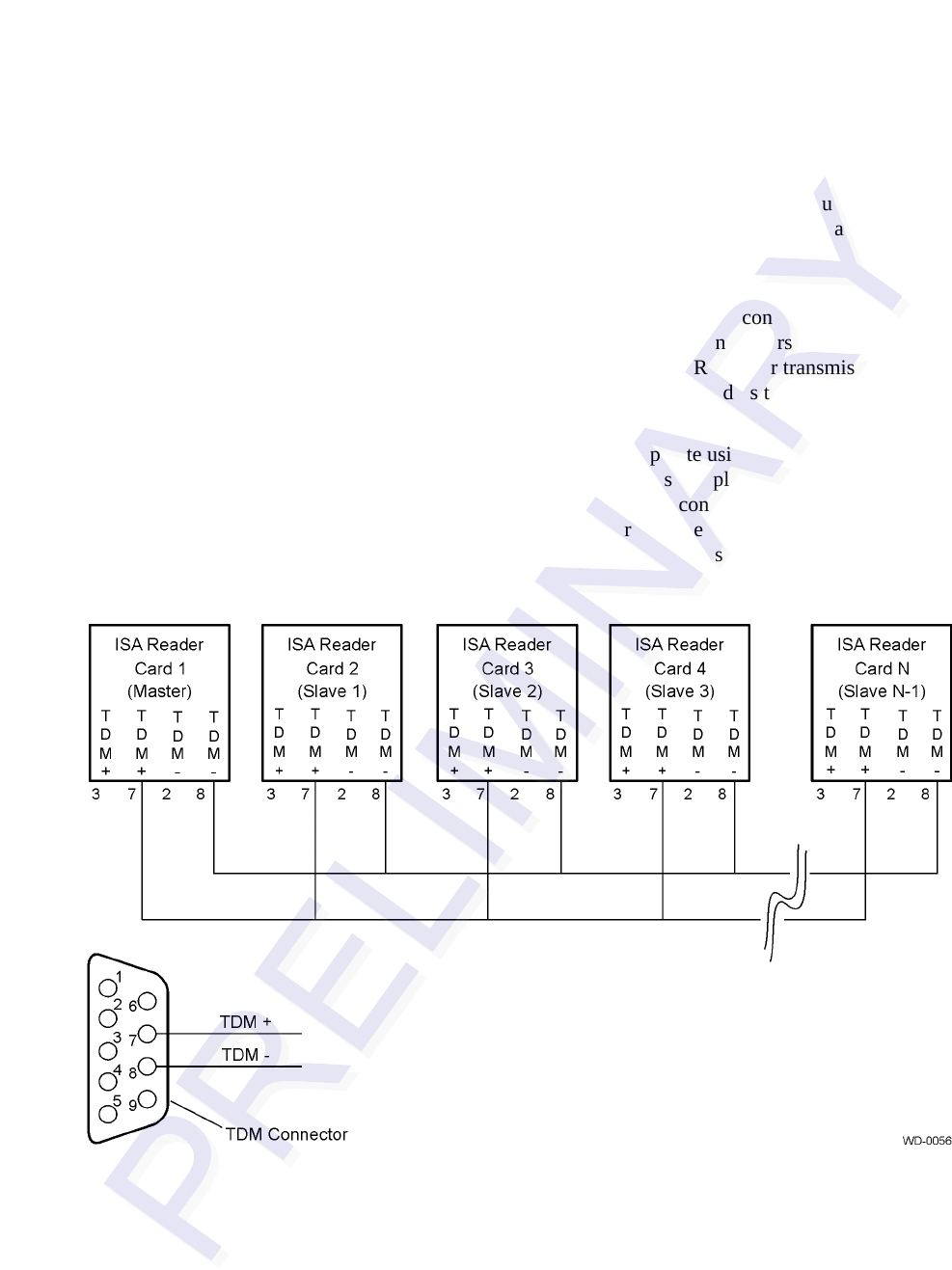
Although you need to configure the readers to operate using TDM, the interface con-
nection for TDM can be provided to all the readers in a plaza before or during installa-
tion by connecting a pair of wires to the DB9 TDM connector of each reader as shown
in
Figure 5-2. No other equipment is necessary for the interconnection circuit. You
need to follow the polarity conventions as shown because this interface is polarity
dependent.
Figure 5-2 TDM Configuration Example
TransCore recommends Belden 89182 or 8132 cable. Using these low-loss, low-
capacitance twisted-pair cable, the maximum distance is 1000 feet (305 m). Cables
with lower capacitance can be used to run the TDM cables for longer distances while
maintaining signal integrity. This maximum distance may be slightly longer or shorter
depending on the cable used.