
User's Manual

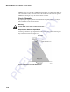


Table Of Contents
- Health Limits
- Contents
- Before You Begin
- Developing the Installation Site Plan
- Installing and Configuring the MPI 6000
- Lane Tuning Guidelines
- Optimizing MPI 6000 Reader System Performance
- General Software Information
- Configuration Commands and Responses
- Configuring the MPI 6000
- Required Commands to Set Up MPI 6000 Reader
- System Interface Command Group Commands
- System Identify
- Set Communications Baud Rate
- Get Communications Baud Rate
- Set Time and Date
- Get Time and Date
- Firmware Download
- Reset Reader
- Get Stored Tag Response Message
- Get Number of Stored Tag Response Messages
- Delete All Stored Tag Response Messages
- Get System Startup Status
- Get Lane Controller Interface Status
- Get System Interface Status
- Get DigBrd Hdwr Remote Inventory
- Get DigBrd CPU Boot Fmwr Remote Inventory
- Get DigBrd CPU Appl Fmwr Remote Inventory
- Get DigBrd FPGA UDP/IP Core Fmwr Remote Inventory
- Get UDP/IP Core Lane Controller Parameters
- Set UDP/IP Core IP Address
- Get UDP/IP Core IP Address
- Get UDP/IP Core Port Number
- Configuring the MPI 6000
- Tag Command Processing
- System Diagnostics and Preventive Maintenance
- Acronyms and Glossary
- Block Diagrams
- System Technical Specifications
- Hardware Interfaces
Optimizing MPI 6000 Reader System Performance
5-11
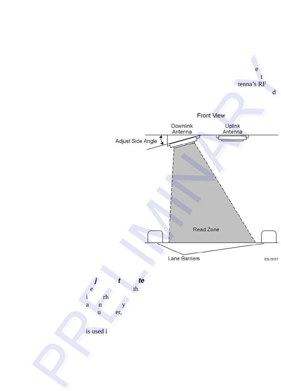
Adjusting the Antenna Side Angle
In the eGo 4110A Reader System, you can adjust an antenna’s side angle so that the
RF transmits toward the center of the toll lane, placing the RF footprint into the lane.
If the side angle is too small, the footprint can project into the lane nearest to the tilted
antenna. If the side angle is too large and the RF footprint is projecting toward the
other antenna, you can reduce the side angle so that the antenna’s RF footprint is
evenly placed within the correct lane boundaries.
Figure 5-6 shows the downlink
antenna being tilted toward the center of the lane.
Figure 5-6 Downlink Antenna Side Angle Adjustment
Adjusting the Antenna Placement
Besides adjusting the antenna angles, you can also move the antenna farther back into
its overhead location so that the read zone does not extend as far in front of the trans
-
action area. By shortening the read zone, you may be able to reduce the required RF
output power, which will result in reduced probability of cross-lane interference.
You can also move the antenna pair from side to side within the lane. This adjustment
is used in lanes where the traffic travels closer to one side than another. For example,
in manned toll lanes, traffic tends to drive closer to the left side of the lane. The cen
-
terline between the antennas can be shifted to the left to compensate for this tendency.
Other Site Modifications
In rare instances, applying radar-absorbing foam to fixed areas of the toll plaza (e.g.,
metal roof) may reduce the incidence of interference.