MIL-SW8T1GPA 8 Port 10/100/1000BASE-T with 1 Combo 1000BASE-X SFP Port Web Managed Switch User Guide Rev.
Regulatory Approval - FCC Class A - UL 1950 - CSA C22.2 No. 950 - EN60950 - CE - EN55022 Class A - EN55024 Canadian EMI Notice This Class A digital apparatus meets all the requirements of the Canadian Interference-Causing Equipment Regulations. Cet appareil numerique de la classe A respecte toutes les exigences du Reglement sur le materiel brouilleur du Canada.
Content INTRODUCTION .............................................................................. 3 Features...................................................................................................................3 Software Feature......................................................................................................4 Package Contents....................................................................................................5 HARDWARE DESCRIPTION .........................
Spanning Tree ....................................................................................................... 25 RSTP System Configuration........................................................................... 25 RSTP Port Configuration ................................................................................ 27 Spanning Tree Status ............................................................................................ 27 802.1X Configuration .........................................
Introduction The 8 10/100/1000T with 1 1000Base-X SFP/RJ45 Combo port Web Managed Switch that can be used to build high-performance switched workgroup networks. The switch is targeted at workgroup or department. The 8 10/100/1000Base-T with 1 1000Base-X SFP/RJ45 Combo port Web Managed Switch features a Store-and-Forward Switching scheme that offers low latency for high-speed networking and allows the switch to auto-learn and store source address in a 8K-entry MAC address table.
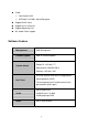
VLAN Port Based VLAN IEEE 802.1Q VLANs. Up to 256 groups Support DHCP client Support Class of Service Support Spanning Tree 9K Jumbo Frame support Software Feature Management Web Management Firmware update Web UI firmware update One default button for system default System default Default IP: 192.168.1.77 Subnet Mask: 255.255.255.0 Gateway: 192.168.1.254 IEEE802.
Port based Quality of Service Tag based IPv4 Type of Service Class of Service Per port support 4 priority queues IEEE802.1w rapid spanning tree and compatible Spanning Tree with IEEE 802.
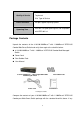
item is missing or damaged, please contact the local dealer for exchanging.
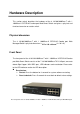
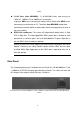
Hardware Description This section mainly describes the hardware of the 8 10/100/1000Base-T with 1 1000Base-X SFP/RJ45 Combo port Web-Smart Switch and gives a physical and functional overview on certain switch. Physical dimension The 8 10/100/1000Base-T with 1 1000Base-X SFP/RJ45 Combo port Web Managed Switch’s physical dimension is 217 x 140 x 43 mm (L x W x H).
Switch RJ-45 Ports (Auto MDI/MDIX): 7x 10/100/1000 N-way auto-sensing for 10Base-T, 100Base-TX or 1000Base-T connections. In general, MDI means connecting to another Hub or Switch while MDIX means connecting to a workstation or PC. Therefore, Auto MDI/MDIX would allow connecting to another Switch or workstation without changing non-crossover or crossover cabling. SFP/RJ-45 combo port: The system will automatically detect which is Giga UTP or Giga fiber.
LED Indicators The LED Indicators display real-time information of systematic operation status. The following table provides descriptions of LED status and their meaning.
Blinks LNK /ACT (MINI GBIC) Orange -- On Green attached Green Off port Half-duplex mode or no device Off Blinks Collision of Packets occurs in the The port is successfully connecting with the device The port is receiving or transmitting data No data transmitted or no device -- connected The Description of LED Indicators Desktop Installation Set the switch on a sufficiently large flat space with a power outlet nearby.
other side of power adaptor connects to the power outlet. The external power supply in the switch works with the AC power from 100 to 240V. Please check with the power indicator on the front panel to see if power is properly supplied.
Network Application This section provides user a few samples of network topology in which the switch is used. In general, the 8 10/100/1000Base-T with 1 1000Base-X SFP/RJ45 Combo port Web Managed Switch is designed as a segment switch. That is, with its address table (8k MAC address) and high performance, it is ideal for interconnecting networking segments.
Segment Bridge For enterprise networks where large data broadcasts are constantly processed, this switch is an ideal solution for department users to connect to the corporate backbone. Use two 8 10/100/1000Base-T with 1 1000Base-X SFP/RJ45 Combo port Web Managed Switch with PCs, print server, and local server attached, are both connecting to the core switch. All the devices in this network can communicate with each other through the core switch.
14
Web-Based Management This section introduces the function configuration of the 8 10/100/1000Base-T with 1 1000Base-X SFP/RJ45 Combo port Web Managed Switch. About Web-based Management On the CPU board of the switch there is an embedded HTML web site residing in flash memory, which offers advanced management features and allow users to manage the switch from anywhere on the network through a standard browser such as Microsoft Internet Explorer. The Web-Based Management supports Internet Explorer 5.0.
1. Launch the Internet Explorer 2. Key in “http://” + “IP Address” of the 8 10/100/1000Base-T with 1 1000Base-X SFP/RJ45 Combo port Web Managed Switch, and then press “Enter” 3. Login screen will appear right after 4. Key in the password(The default password is “root”) 5. And then, click Apply , and then configuration is ready to be set up Main Interface System Configuration Display system parameters information as listed below, and the other parameters of system can be configured as well.
time the client/switch boots and the lease is 50% or more passed, the client/switch will attempt to renew the lease. At 87.5% of the lease completion, the client/switch will attempt to contact any DHCP server for a new lease System Configuration interface DHCP Enable: To enable DHCP Client Function Fallback IP Address: Assigning the switch IP address(The default IP is 192.168.1.
remote management that include telnet, SNMP, and Web browse the switch only when the port of VLAN group ID is equal to the Management VLAN ID Name: the name of the switch Password: Web GUI login password. The default password is root Inactivity Timeout: The web connection timeout time And then, click Or, click Apply Refresh to apply the configuration to reset the configuration before applying Port Configuration Configure the port of status.
Port Configuration interface Statistics Overview The following information provides the current port statistic information Clear Press And then, click button to clean all counts Refresh to get the new setting information as below: Statistics Overview interface 19
Statistics Detail The following information provides statistic detail information of statistic on each port, and simply selecting the port to viewing the statistic information.
And then, click Apply to bring up the configuration interface as below: VLAN Setting interface VLAN Port Setting Click VLAN Port Setting to bring up the configuration interface for adjusting the VID Setting PVID: Enter the Port VLAN ID Awareness: Enable the awareness that ports will strip the VLAN tag from received frames and insert the tag in transmitted frames (PVID).
in transmitted frames Frame Type: To set the outgoing frames Tagged: Outgoing frames with VLAN-Tagged All: All type of frames After that, click Or, click Apply Refresh to apply the configuration to reset the configuration before applying VLAN Port Setting interface Port Trunk Port trunk allows multiple links to be bundled together and act as a single physical link for increased throughput. It provides load balancing, and redundancy of links in a switched inter-network.
Grouping the members of Trunk.
Or, click Refresh to reset the configuration before applying LACP Setting interface LACP Status When the LACP aggregator had been setup, the LACP status information will display as below: 24
LACP Status interface Spanning Tree The Rapid Spanning Tree Protocol (RSTP) is an evolution of the Spanning Tree Protocol and provides for faster spanning tree convergence after a topology change. The system also supports STP and the system will auto detect the connected device that is running STP or RSTP protocol. RSTP System Configuration System Priority: A value used to identify the root bridge.
lowest value has the highest priority and is selected as the root. If the value has being changed, user has to reboot the switch. The value must be multiple of 4096 according to the protocol standard rule. Hello Time (1-10): The scale of 1~10 sec will be set as a period of time that how often the switch broadcasts hello messages to other switches Max Age (6-40): The number of seconds (from 6~ 40) which determines the amount of time that protocol information received on a port is stored by the switch.
RSTP Port Configuration Protocol Enable: To enable or disable the port protocol Edge: The port directly connected to end stations cannot create bridging loop in the network. To configure the port as an edge port, mark the port Path Cost: The cost of the path to the other bridge from this transmitting bridge at the specified port.
RSTP Status interface 802.1X Configuration 802.1x is an IEEE authentication specification that allows a client to connect to a wireless access point or wired switch but prevents the client from gaining access to the Internet until it provides credentials, like a user name and password that are verified by a separate server. Mode: To disable or enable 802.
Or, click Refresh to reset the configuration before applying 802.
QoS Setting Configuring QoS mode of the port and per port priority, TOS and COS priority setting.
QoS Configuration interface Click DSCP Mapping to enter TOS priority configuration interface DSCP [0- 63]: The system provides 0~63 TOS priority level. When the IP packet is received, the system will check the TOS level value in the IP packet that has received. For example: user set the TOS level 25 is high. The port 1 is following the TOS priority policy. When the packet received by port 1, the system will check the TOS value of the received IP packet.
QoS DSCP Mapping interface Click VLAN tag Mapping to enter VLAN tag priority configuration interface. Select the VLAN tag priority level: High, Medium, Normal and Low.
System Restart Reboot the switch in software reset. All the configurations will be reminded Click Yes to restart the system System Restart interface Factory Default Reset switch to default configuration Click Yes to reset the all configuration to the default value Factory Default interface Firmware Upload The system provides the Web GUI firmware update function which would allow the user to update the switch firmware.
And then, press Upload to update the firmware Firmware Upload interface Configuration File Transfer The system provides the Web GUI configuration upload function which would allow the user to backup the switch configuration.
Troubleshooting This section is intended to help user solve the most common problems on the 8 10/100/1000Base-T with 1 1000Base-X SFP/RJ45 Combo port Web Managed Switch with. Incorrect connections The switch port can auto detect straight or crossover cable when link switch with other Ethernet device. For the RJ-45 connector should use correct UTP or STP cable, 10/100Mbps port use 2 pairs twisted cable and Gigabit 1000T port use 4 pairs twisted cable.
100Ω Category 5 cable for 100Mbps connections. Also be sure that the length of any twisted-pair connection does not exceed 100 meters (328 feet). Gigabit port should use Cat-5 or cat-5e cable for 1000Mbps connections. The length does not exceed 100 meters. Improper Network Topologies It is important to make sure that have a valid network topology. Common topology faults include excessive cable length and too many repeaters (hubs) between end nodes.
Technical Specification This section provides the specifications of 8 10/100/1000Base-T with 1 1000Base-X SFP/RJ45 Combo port Web Managed Switch with. IEEE 802.3 10BASE-T Ethernet IEEE 802.3u 100BASE-TX Fast Ethernet IEEE 802.3ab 1000Base-T IEEE 802.3z Gigabit Fiber Standard IEEE 802.3x Flow Control and Back-pressure IEEE 802.1w Rapid Spanning Tree IEEE 802.3ad Port trunk with LACP IEEE 802.1p Class of Service IEEE 802.1x user authentication IEEE 802.
Per unit: Power 10BASE-T: 2-pair UTP/STP Cat. 3, 4, 5 cable EIA/TIA-568 100-ohm (100m) Network Cable 100BASE-TX: 2-pair UTP/STP CAT. 5 cable EIA/TIA-568 100-ohm (100m) Gigabit Copper: 4 pair UTP/STP CAT. 5 cable EIA/TIA 568 100-ohm (100M) Connector Gigabit copper: 8 x RJ-45 with Auto-MDIX SFP port: 1 x SFP slot (3.
Operating Humidity EMI Safety 10% to 90% (Non-condensing) FCC Class A CE UL cUL 10900 Red Circle Drive Minnetonka, MN 55344 Tel.: +1.952.941.7600 techsupport@transition.