
Network Card User Manual
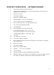

PCI NETWORK INTERFACE CARDS
TRANSITION Networks Fiber-Optic PCI Network Interface Cards (Adapters) are 32-bit bus-mastering PCI
cards that support both half-duplex and full-duplex operation and that comply with PCI Specifications,
revision 2.1 and 2.2, and with both IEEE 802.3 10BASE-FL,
100BASE-SX, and 100BASE-FX standards
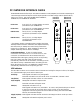
N-FX-xx-01 One (1) ST, SC, or MT-RJ adapter connection
(indicated as xx) to 100BASE-FX.
N-SX-xx-01* One (1) ST, SC, or MT-RJ adapter connection
(indicated as xx) to 10/100BASE-SX.
ND-FX-xx-01
†
Two (2) ST, SC, or MT-RJ adapter
connections (indicated as xx) to 100BASE-
FX.
ND-SX-xx-01*
†
Two (2) ST, SC, or MT-RJ adapter
connections (indicated as xx) to
10/100BASE-SX.
* The adapter remains at 100Mbps when possible. Should the
100Mbps network become unavailable, the adapter seamlessly
switches activity to 10Mbps and continuously monitors the
network for a restored link. When 100Mbps is restored, the
adapter seamlessly switches back to 100Mbps.
†Network Redundancy If cable is installed at both
connections on the
ND-FX-xx-01 or on the ND-SX-xx-01, each
connection is redundant to the other. Network activity is
established first at the upper, primary port link. If the primary
port link is down more than a few seconds, the NIC
automatically switches over to the bottom, secondary port link
and network activity is established at the secondary port link.
When the primary port link is re-established, network activity
automatically switches back to the primary port link.
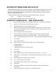
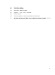
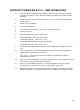
LED Indicators
The two LEDs closest to each connector shows link status and activity for that port. Collision, full-duplex,
and selection LEDs apply to the active network port.
ACT(ivity) Flashing LED indicates link is passing traffic
Dark LED indicates link is idle. NOTE: If link is unavailable, indicator is dark.
COL(lisiion) Flashing LED indicates collision in active network.
F(ull) D(uplex) Steady LED indicates full duplex mode.
Dark LED indicates half duplex mode.
STAT(us) Steady LED indicates link is up.
Flashing LED indicates link is unavailable. To correct, verify that the RX port is cabled
to the TX port at the far end of the cable, and vice versa. Also verify that the
equipment is functioning at the far end and that the cabling does not exceed IEEE
802.3(u) recommended lengths.
M(agic) P(acket) Flashing LED indicates the NIC received a valid Magic Packet to “wake up” the PC.
SEL(ect) Steady LED indicates that adjacent port is active.
3
RX TXRX TX
MP
SEL
FD
COL
ACT
STA
SEL
ACT
STA
RX TX
MP
SEL
FD
COL
ACT
STA
N-FX-xx-01 ND-FX-xx-01
N-SX-xx-01 ND-SX-xx-01