Quick Start for Hardware Installation Avaya P332MF Stackable Switch 10-300712 Issue 1 September 2005
Copyright 2005, Avaya Inc. All Rights Reserved Notice Every effort was made to ensure that the information in this document was complete and accurate at the time of printing. However, information is subject to change. Warranty Avaya Inc. provides a limited warranty on this product. Refer to your sales agreement to establish the terms of the limited warranty.
Contents Chapter 1: Before you Start . . . . . . . . . . . . . . . . . . . . . . . . . 5 Gathering Information . . . . . . . . . . . . . . . . . . . . . . . . . . . . . . . . . Defining the Installation . . . . . . . . . . . . . . . . . . . . . . . . . . . . . . Preparing Contacts you might need . . . . . . . . . . . . . . . . . . . . . . . 5 5 5 Preparing Installation Files . . . . . . . . . . . . . . . . . . . . . . . . . . . . . . 6 Preparing Needed Tools . . . . . . . . . . . . . . . . . . . . .
Contents Installing from the P330 Documentation and Utilities CD. . . . . . . . . . . . Install from the Avaya Web Site . . . . . . . . . . . . . . . . . . . . . . . . . Install from your Local Web Site . . . . . . . . . . . . . . . . . . . . . . . . . 32 33 33 Installing the On-Line Help and Java Plug-In on your Web Site . . . . . . . . . . 33 Documentation. . . . . . . . . . . . . . . . . . . . . . . . . . . . . . . . . . . . .
Chapter 1: Before you Start Before you install your Avaya Switch, prepare all the information, resources, and tools that you need during the installation process. Good preparation ensures a smooth installation with the least amount of interruption. ! WARNING: ONLY TRAINED AND QUALIFIED PERSONNEL SHOULD BE ALLOWED TO INSTALL OR REPLACE THIS EQUIPMENT. ! WARNING: EQUIPMENT MUST BE CONNECTED TO AN EARTHED MAINS SOCKET-OUTLET.
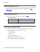
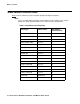
Before you Start Preparing Installation Files Ensure that you load the latest versions of the firmware file for the P330. You can download the firmware file needed for your installation from the Avaya Support Web site, at http:// support.avaya.com. Preparing Needed Tools Prepare the tools you need to mount the P330, according to the Table 1: Table 1: Mounting Tools If you need to mount on...
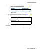
Choosing the Installation Site ● The environmental conditions match the requirements listed in Table 2.
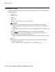
Before you Start Building a stack Follow the guidelines in this section in order to build a working stack using any combination of the following devices: ● P330 series ● P330-ML series ● G700 ● P330 series 1. Add only a single box at a time to an existing stack. ! Important: Important: The stack master (also called "stack IP Agent") may fail to preserve existing "stack configuration" if you will add more than a single device to an existing stack at a time.
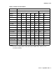
Building a stack Table 4: Firmware Versions Matrix Required version Stack without C360 Note: Stack with C360 Switch 3.11 3.12 4.0 4.1 4.5 4.3 4.5 P333T 3.11.0 3.12.1 4.0.17 4.1.6 4.1.6 N/A N/A P334T 3.11.0 3.12.1 4.0.17 4.1.6 4.1.6 N/A N/A P333R 3.11.0 3.12.0 4.0.9 4.1.5 4.1.5 N/A N/A P333R-LB 3.11.0 3.12.3 4.0.6 4.1.5 4.1.5 N/A N/A P332MF 3.11.0 3.12.1 4.0.17 4.1.6 4.1.6 N/A N/A P333T-PWR 3.11.0 3.12.1 4.0.17 4.1.6 4.1.6 N/A 4.1.6 G700 3.11.0 3.
Before you Start Stack Master election rules Table 5 lists the switches in order of election priority from highest to lowest. Note: Note: If there are two switches with the same firmware version and the same election priority, the switch positioned lower in the stack becomes Stack Master.
Stack Master election rules Figure 1: Example stack elections C364T-PWR Layer 3 C363T-PWR Layer 2 P363T-PWR Layer 2 P333T 1 P334T-ML Layer 3 G700 P333T P334T-ML Layer 3 G700 1 C363T-PWR Layer 2 Figure notes: 1.
Before you Start 12 Quick Start for Hardware Installation: P332MF Stackable Switch
Chapter 2: Unpack the Device ! ELECTROSTATIC ALERT: ELECTROSTATIC ALERT: Wear an anti-static wrist ground strap whenever you handle components of a P330. Connect the strap to an approved ground, such as an unpainted metal surface. Equipment Open the box that contains the P330, and ensure that it contains the following components and accessories: ● One Avaya P332MF Switch.
Unpack the Device One RJ45 to DB9F Adapter One DB25M Adapter Four (4) 5/16" Round Head Screws Four (4) Washers Four (4) stand-off feet Documentation ● Avaya P332MF Quick Start Guide (this document) ● Avaya P330 Release Notes 14 Quick Start for Hardware Installation: P332MF Stackable Switch
Documentation ● Avaya P330 Documentation and Utilities CD (see detail below) ● Avaya Communication Warranty and License Agreement Avaya P330 Documentation and Utilities CD The CD contains the latest User's Guides for the Avaya P330 stackable switches and files for use with the Embedded Web Manager. ● User's Guides You can view and print these Guides using Adobe® Acrobat® Reader.
Unpack the Device 16 Quick Start for Hardware Installation: P332MF Stackable Switch
Chapter 3: Mount the Device You can mount the P330 in a rack. The P330 chassis fits in most standard 19-inch racks. It is 2U (3.5”, 88 mm) high. Before you Install the P330 in a Rack ● Disconnect all cables from the unit before proceeding with the rack installation. ● When installing P330 in a rack, ensure that the equipment is positioned such that it will not cause the rack to become unstable or tip over.
Running H/F 1 Figure 3: Open hinged end P333T 51 52 53 54 55 56 57 58 59 60 61 62 63 64 65 66 1 2 3 4 5 6 7 8 9 10 11 12 EXPANSION SLOT FIV 13 14 15 16 LNK COL Tx 17 18 19 20 Rx FDX FC Hspd LAG 1 21 22 23 24 SYS OPR PWR LAG 1 2 LAG 3 4 5 6 LAG 7 8 9 10 11 12 CONSOLE 13 14 15 16 17 18 19 20 21 22 23 24 Figure notes: 1. Open hinged end 2. Position the unit in the rack. 3. Secure the unit to the rack, taking care not to overtighten the screws. 4.
Chapter 4: Power Up Connecting the P330 to the main electrical supply provides power to the switch. ! VOLTAGE ALERT: VOLTAGE ALERT: To isolate the switch completely, you must disconnect all power connections: AC plug or DC terminal block and DC BUPS power. P330 AC version 1. Insert the power cord into the power connector (BUPS or Power Supply) on the rear of the unit. Figure 4: P330 AC version rear panel 1 2 Figure notes: 1. BUPS connector 2. AC connector 2.
Power Up P330 DC version ! VOLTAGE ALERT: Before performing any of the following procedures, ensure that DC power is OFF. ! CAUTION: This product is intended for installation in restricted access areas and is approved for use with 18 AWG copper conductors only. The installation must comply with all applicable codes. VOLTAGE ALERT: CAUTION: Figure 5: P330 DC version rear panel 1 Figure notes: 1. DC input terminal block 1.
P330 DC version 3. negative to negative ! WARNING: WARNING: Always connect the ground wire first and disconnect it last.
Power Up 22 Quick Start for Hardware Installation: P332MF Stackable Switch
Chapter 5: Prepare for Configuration This chapter provides information on preparing the P330 for configuration, and discusses the following topics: ● Establishing a Console Connection ● Assigning a P330 IP Stack Address ● Establishing a Telnet Connection ● Configuring the Switch Establishing a Console Connection This section describes the procedure for establishing switch access between a terminal and the Avaya P330 switch over the serial port provided on the front panel of the P330 (RJ-45 connector
Prepare for Configuration 1. Use the serial cable supplied to attach the RJ-45 console connector to the Console port of the active P330 switch. Connect the DB-9 connector to the serial (COM) port on your PC/ terminal. - The master P330 is indicated by the SYS LED being ON. 2. Ensure that the serial port settings on the terminal are: ● 9600 baud ● 8 bits ● 1 stop bit ● no parity.
Establishing a Telnet Connection 4. At the prompt, type: set interface inband Replace , and with the VLAN, IP address, and net mask of the stack. 5. Press Enter to save the IP address and net mask. 6. At the prompt, type reset. Type y and press Enter to reset the stack. After the Reset, log in again as described above. - At the prompt, type set ip route and replace and with the destination and gateway IP addresses.
Prepare for Configuration Configuring the Switch This section describes the procedures for the first-time configuration of the Avaya P330. The factory defaults are set out in detail in the tables included in this chapter. You may configure the Avaya P330 using the text-based Command Line Interface (CLI), the built-in Avaya P330 Device Manager or Avaya Integrated Management. For instructions on the CLI, see the Avaya P330 Reference Guide.
Configuring the Switch 5. Press Enter to save the destination and gateway IP addresses. Avaya P330 Default Settings If you wish to change the default parameters shown and configure the mandatory parameters, we recommend that you use the Command Line Interface (CLI). For further information, please refer to Chapter 6 of the Avaya P330 User’s Guide. The default settings for the Avaya P330 switch and its ports are determined by the Avaya P330 firmware.
Prepare for Configuration Table 7: Default Port Settings Parameter Default Setting Port speed and duplex mode ● ● ● Flow Control ● ● Backpressure ● ● Auto-negotiation ● ● ● Tip: 10/100-TX ports: Auto-negotiation 100Base-FXports:100 Mbps full duplex 1000Base-X ports: 1000 Mbps full duplex 10/100 and 100 Mbps: Disabled 1000 Mbps: Disabled (no pause) 10/100: Enabled (when in half duplex mode) 100Base-FX &1000 Mbps: Not applicable 10/100-TX ports: Enabled 100Base-FX ports: Not applicable 1000Base-X
Chapter 6: Device Manager This chapter describes the installation procedures for the Device Manager of the Avaya P330. Overview The Device Manager provides the following: ● Managing and monitoring Power over Ethernet. ● Device Configuration - Viewing and modifying the different device configurations. ● Virtual LANs - Viewing and editing Virtual LAN information. ● Link Aggregation Groups (LAGs) - Viewing and editing LAG information.
Device Manager Configuring the Device Manager You can configure several Device Manager parameters using the CLI. These parameters include the time-out and retries parameters, the location of the Web server that provides the help files for the Device Manager, and the Java plug-in required for running the Device Manager. Device Manager Commands The following Device Manager commands are available. In order to... Use the following command...
Running the Device Manager - The user name is “root”. - The default password for read-only access is “root”. - The default passwords for read-write access is “root”. Note: Note: The P330 Device Manager passwords are the same as those of the CLI. If you change the passwords of the CLI then those passwords become active for the Device Manager as well. For further information on the passwords, refer to the Avaya P330 Installation and Configuration User Guide. The welcome page is displayed.
Device Manager Figure 8: Device Manager 3. If you do not have the Java plug-in installed, follow the instructions on the Welcome page for a variety of options to install the plug-in (see Installing the Java Plug-in). Installing the Java Plug-in If the network manager has configured the system, the plug-in should be installed automatically. Note: Ensure that Java or JavaScript is enabled on your Web browser. Please refer to your browser on-line help or documentation for further information.
Installing the On-Line Help and Java Plug-In on your Web Site 4. Browse to the embweb-aux-files\ folder on the CD. 5. Double-click plugin_a_b_c.exe (a, b and c are the version numbers of the plug-in). 6. Follow the on-screen instructions. Install from the Avaya Web Site Click the link in the Welcome page labelled “Retrieve it from here”. Install from your Local Web Site Click the appropriate link in the Welcome page.
Device Manager Documentation The Device Manager comes with a detailed User’s Guide including a Glossary of Terms and an overview of Data Communications concepts.