
User Guide


8
S4TEF10xx-11x
24-hour Technical Support: 1-800-260-1312 International: 00-1-952-941-7600
Installation — Continued
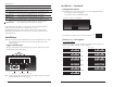
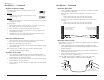
Hardware/software jumper
The jumper is located on the circuit board, inside the media
converter housing.
Hardware:
The media converter mode is determined by the switch
setting (see pages 3 - 7).
Software:
The media converter mode is determined by the most-recently saved, on-board
microprocessor settings.
To set the jumper:
1. Using a small screwdriver, remove the four (4) screws that secure the cover
and carefully remove the cover from the media converter.
2. Locate the jumper near the back end on the upper circuit board.
3. Using small needle-nosed pliers or similar device, move the jumper to the
desired position (see above).
4. Carefully replace the cover on the media converter and replace the four (4)
screws that secure the cover to the media converter.
Power the media converter
1. Connect the barrel connector on the power adapter to the media converter’s
power port (located on the back of the media converter).
2. Connect the power adapter plug to AC power.
3. Verify that the media converter is powered by observing the illuminated LED
power indicator light.
Note: For DC power, consult the user’s guide for the Transition Networks
SPS1872-xx DC external power supply.
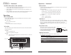
Install the T1/E1 cable
1. Locate or build ITU-compliant copper cable with straight-through RJ-48
connectors installed at both ends. (See pages 19 thru 21 for the proper cable
specifications for your network application.).
2. Connect the RJ-48 connector at one end of the cable to one of the T1/E1 ports
on the S4TEF10xx-11x media converter.
3. Connect the RJ-48 connector at the other end of the cable to the T1/E1 port on
the other device.
Hardware Mode
Software Mode
S
H
S
H
9
techsupport@transition.com -- Click the “Transition Now” link for a live Web chat.
Installation -- Continued
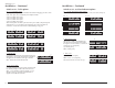
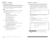
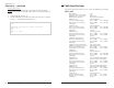
Install the fiber cable
1. Locate or build ITU-compliant fiber cable with male, two-stranded TX to RX
connectors installed at both ends.
2. Connect the fiber cables to the local S4TEF10xx-11x media converter as
described:
• Connect the male TX cable connector to the female TX port.
• Connect the male RX cable connector to the female RX port.
3. Connect the fiber cables to the remote S4TEF10xx-11x media converter as
described:
• Connect the male TX cable connector to the female RX port.
• Connect the male RX cable connector to the female TX port.
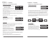
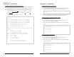
Install the ethernet cable
Ensure that the correct cable type is installed to support the highest speed and mode
of operation to be selected.
1. Locate or build IEEE 803.2™ compliant 10Base-T or 100Base-TX cables,
with straight-through RJ-45 cable, and with straight-through RJ-45 connectors
installed at both ends.
2. Connect the RJ-45 connector at one end of the cable to the RJ-45 port on the
S4TEF10xx-11x media converter.
3. Connect the RJ-45 connector at the other end of the cable to the RJ-45 port on
the other device (switch, workstation, etc.).
Note: The MDI (straight-through) or MDI-X (crossover) cable connection is
configured automatically, according to the network conditions.
RJ-45 port
on the other device
(switch, work station, etc.)
RJ-45 port
on the media
converter
Connect the fiber cable
to the local media
converter as shown.
Connect the fiber cable
to the remote media
converter as shown
RX
TX
RX
TX