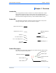
TRANZEO TR-49 Tranzeo TR-49 Series User Guide Covers the following models: TR-49-20, TR-49-N, TR-490, TR-49PLUS-24N Revision: 2.0 Firmware: 5.
Document Revisions: Version 2.0 November 16, 2009 Tranzeo Wireless Technologies Inc. 19473 Fraser Way Pitt Meadows, BC Canada V3Y 2V4 Toll Free Number: 1.866.872.6936 Technical Support: 1.888.460.6366 Local Number: 1.604.460.6002 Fax Number: 1.604.460.6005 iiiiii This document is intended for Public Distribution Pitt Meadows, B.C. Canada V3Y 2V4 General Inquiries: info@tranzeo.com Sales: sales@tranzeo.com Technical Support: support@tranzeo.
Tranzeo Wireless Technologies Safety Information Safety Information FCC Compliance This equipment has been tested and found to comply with the limits for a digital device pursuant to part 90 of the FCC Rules. These limits are designed to provide reasonable protection against harmful interference when the equipment is operated in a Residential environment.
Tranzeo Wireless Technologies ! Safety Information Safety Instructions You must read and understand the following safety instructions before installing the device: • • • • • This antenna’s grounding system must be installed according to Articles 810-15, 810-20, 810-21 of the National Electric Code, ANSI/NFPA No. 70-1993. If you have any questions or doubts about your antenna’s grounding system, contact a local licensed electrician. Never attach the grounding wire while the device is powered.
Tranzeo Wireless Technologies Table of Contents Table of Contents Chapter 1: Overview ........................................................................ 1-1 Introduction.................................................................................................. 1-1 Product Kit ................................................................................................... 1-1 Product Description......................................................................................
Tranzeo Wireless Technologies Table of Contents Access Control........................................................................................3-19 DFS / TPC ..............................................................................................3-20 Status ..........................................................................................................3-21 Station List .............................................................................................3-21 AP List .........
Tranzeo Wireless Technologies Table of Contents Appendix K: Tranzeo Electrical Plugs ............................................. K-1 Appendix L: Warranty Terms ............................................................ L-1 Appendix M: How Can We Improve? ............................................... M-1 Appendix N: Notes ............................................................................. N-1 TR-49 Series Pitt Meadows, B.C.
Tranzeo Wireless Technologies Chapter 1: Overview Chapter 1: Overview Introduction This next-generation wireless LAN device–the Tranzeo TR-49 series– brings Ethernet-like performance to the wireless realm. Fully compliant with the IEEE802.11a standard, the TR-49 series also provides powerful features such as the Internet-based configuration utility as well as WEP and WPA security. Product Kit The TR-49 Series product kit contains the items shown below.
Tranzeo Wireless Technologies Chapter 1: Overview LED Panel Indicators Operational Power LAN Radio Color Indicators ● Red On: Powered on Off: No power or LED’s Disabled ● Green On: Ethernet link Flashing: Ethernet traffic Off: No Ethernet link ● Amber On: Radio link Flashing: Radio activity Off: No radio link ● Red Signal (CPE or PxP Mode) ● Amber In CPE mode LEDS light up in sequence ● Amber to indicate signal strength ● Green based on Signal Noise.
Tranzeo Wireless Technologies Chapter 2: Hardware Installation Chapter 2: Hardware Installation The TR-49 Series radios are easy to install, as you’ll see in this chapter. Before starting, you will need to get the tools listed below and decide about the site and orientation of the device. Once ready, follow the instructions about how to install the Ethernet cable, mount the device, ground the antenna, and make the connections in order to get a proper installation.
Tranzeo Wireless Technologies Chapter 2: Hardware Installation Polarity Determine if the antenna’s polarization will be horizontal or vertical before installation. The TR-49 radios can be used in either polarity. The Ethernet boot cover should always be placed so that the cable runs toward the ground for maximum environmental protection. Power Supply Only use a power adapter approved for use with the TR-49 Series radio. Otherwise, the product may be damaged and will not be covered by the Tranzeo warranty.
Tranzeo Wireless Technologies Chapter 2: Hardware Installation Installing the Ethernet Cable Step 1: Insert the strain relief, without the cap nut, into the port opening of the boot cover. Step 2: Using a 3/4” wrench, tighten the strain relief until it touches the boot cover. IMPORTANT! Use hand tools only. Do not over tighten. Step 3: Put the cap nut back over the strain relief and insert the Cat 5 cable through it.
Tranzeo Wireless Technologies Chapter 2: Hardware Installation Step 5: Place the gasket—with the adhesive side facing up—over the 4 studs around the port of the radio. Flatten the gasket ensuring there are no gaps. Remove the backing. Step 6: Plug the Cat 5 cable inserted in the boot cover into the port. Remember to place the boot cover according to the desired polarization, so that the strain relief faces the ground. Step 7: Fit the boot cover over the 4 studs and the gasket. Secure with 4 keps nuts.
Tranzeo Wireless Technologies Chapter 2: Hardware Installation Mounting the Radio Step 9: Attach the mounting bracket to the pole using the U-bolt. Secure the U-bolt with the lock washers and the nuts. Align if necessary, and then tighten the nuts enough to prevent any movement. Step 10: Fit the radio to the mounting bracket. Secure the radio with keps nuts. IMPORTANT! The strain relief must be always facing the ground.
Tranzeo Wireless Technologies Chapter 2: Hardware Installation Connecting the Radio Step 12: Connect the Cat 5 cable from the radio into the RJ-45 jack marked “CPE” on the POE adapter. The POE adapter is not weatherproof and should be installed indoors. Step 13: Connect the power adapter to the POE adapter and plug the other end to an outlet. The POE adapter will be powered on and the power indicator on the top panel will turn on.
Tranzeo Wireless Technologies Chapter 2: Hardware Installation Best Practices Follow these practices to ensure a correct installation and grounding. • • • • • Always try to run long Cat 5 and LMR cables inside of the mounting pole. This helps to insulate the cable from any air surges. Keep all runs as straight as possible. Never put a loop into the cables. Test all grounds to ensure that you are using a proper ground.
Tranzeo Wireless Technologies Chapter 3: Configuration Chapter 3: Configuration The TR-49 Series radios can be configured through an HTML configuration interface, accessible using any Internet browser. The configuration interface allows you to define and change settings, and also shows information about the performance of the device. In this chapter we’ll cover how to access the configuration interface, configure the TR-49 Series radio, and interpret the information displayed in the interface.
Tranzeo Wireless Technologies Chapter 3: Configuration Changing the IP Address Using the Tranzeo Victor Program The Tranzeo Victor Program is a utility that allows users to quickly change the IP address of the Tranzeo radios. It sends out a broadcast on the network and displays a list of other Tranzeo radios connected, from which you can configure the IP address for your device. Note: The Tranzeo Victor Program cannot locate radios through routers.
Tranzeo Wireless Technologies Chapter 3: Configuration Run Menu Scan: Locates Tranzeo radios connected to the network. A * appears before the name when the radio is in the same subnet as your PC. Detail: Displays more info for a selected radio, such as IP Mode, Gateway, etc .This option is only available when a device is selected. Set IP: Using this option you set the device to have a DCHP address, or set the Static Details.
Tranzeo Wireless Technologies Chapter 3: Configuration Login into the Configuration Interface After defining the network settings, follow these steps to login into the Tranzeo Configuration Interface. 1. Open your Internet browser (Internet Explorer, Netscape, or Firefox). 2. In the address bar, type your IP address (default IP: http://192.168.1.100). 3. In the login dialog, enter your Username and Password (if you’re a firsttime user, follow the instructions below). 4. Click OK.
Tranzeo Wireless Technologies Chapter 3: Configuration Information Page This is the first window of the configuration interface. It shows the main menu and information about the device settings, like wireless, network, and security settings. The menu is divided in four sections: • Setup Menu • Security • Status • Network Each section contains navigation links to the configuration windows, some of which may be different for access points and CPEs.
Tranzeo Wireless Technologies Chapter 3: Configuration Setup Menu In this section you would be able to configure wireless and administrative settings for the TR-49 Series radio. Wireless Settings - Basic Tab, Access Point This window displays the wireless configuration of the device. The contents are slightly different for access point and CPE. Wireless Mode: SSID: Visibility Status*: Define if your device will operate as Infrastructure Station (CPE) or Access Point.
Tranzeo Wireless Technologies Chapter 3: Configuration Supported Tx Rates: Select the rates at which you the radio will transmit. *indicates basic rates. All Basic rates supported by the AP must also be supported by the CPE or it will prevent association. Link Distance: This is the distance between the CPE and access point. This setting is necessary to define the correct ACK timing. Setting this value too low or too high will result in low throughput and high retries.
Tranzeo Wireless Technologies Chapter 3: Configuration Wireless Settings - Basic Tab, Infrastructure Station This window displays the wireless configuration of the device. The contents are slightly different for access point and CPE. Wireless Mode: Define if your device will operate as Infrastructure Station (CPE) or Access Point. SSID: The Service Set Identifier (SSID) is the name that identifies a specific wireless LAN. Devices must have the same SSID to communicate with each other.
Tranzeo Wireless Technologies Chapter 3: Configuration Supported Tx Rates: Select the rates at which you the radio will transmit. *indicates basic rates. All Basic rates supported by the AP must also be supported by the CPE or it will prevent association. Link Distance: This is the distance between the CPE and access point. This setting is necessary to define the correct ACK timing. Setting this value too low or too high will result in low throughput and high retries.
Tranzeo Wireless Technologies Chapter 3: Configuration PxP Setup Point to Point (PxP) mode is a Layer 2 transparent protocol optimized for backhaul use. PxP mode is recommended whenever two network segments are to be bridged. To operate the radio in PxP mode: 1. Set one radio to Access Point and the other to Infrastructure Station. 2. Enter the same SSID on both radios. 3. Set the Channel on the access point. 4.
Tranzeo Wireless Technologies Chapter 3: Configuration Wireless Settings - Advanced Tab, Access Point This window displays the advanced wireless configuration of the device. The contents are slightly different for access point and CPE. RTS Threshold: This is the maximum size for a packet to be sent automatically. When it exceeds the RTS threshold, the CPE sends first a ‘request to send’ (RTS) to the access point before sending the packet.
Tranzeo Wireless Technologies Chapter 3: Configuration Wireless Settings - Advanced Tab, Infrastructure (CPE) This window displays the advanced wireless configuration of the device. The contents are slightly different for access point and CPE. RTS Threshold: This is the maximum size for a packet to be sent automatically. When it exceeds the RTS threshold, the CPE sends first a ‘request to send’ (RTS) to the access point before sending the packet.
Tranzeo Wireless Technologies Chapter 3: Configuration Administrative Settings - Firmware Tab Use this window to upgrade the software, change your password, and define SNMP parameters. Upgrade Software: Defaults: Reboot: Rollback: Device Name: User Name: Password: Enter the location of the software update file or Browse to locate it in your computer. Click Upgrade Software. If the radio does not refresh the Information Page after 1 minute, press Refresh, Reload or F5.
Tranzeo Wireless Technologies Chapter 3: Configuration Administrative Settings - Import / Export Use this window to import and export settings. Configuration File Name: Enable TFTP Auto-Config: IP Address: Timeout: Filename: TR-49 Series Pitt Meadows, B.C. Canada V3Y 2V4 Enter the location of the configuration file or Browse to locate it in your computer. Click Import Configuration to import setting or Click Export Configuration to export the settings.
Tranzeo Wireless Technologies Chapter 3: Configuration Administrative Settings - SNMP Tab Use this window to define SNMP parameters. Read Community: This is the read community string. IT IS HIGHLY RECOMMENDED THAT YOU CHANGE THIS VALUE FROM THE DEFAULTS. System Contact: Enter the name of the system contact to be reported by SNMP. Device Location: Enter the location of the device to be reported by SNMP. Counter Format: Select the counter format that you that would like to use.
Tranzeo Wireless Technologies Chapter 3: Configuration WDS (AP only) The Wireless Distribution System (WDS) is a modification to the 802.11 standards that allows access points to communicate directly with each other. WDS allows users to spread out coverage to a larger area without the need for a backhaul link. The tradeoff is that overall throughput is greatly affected for all users of the access points linked.
Tranzeo Wireless Technologies Chapter 3: Configuration Encryption In this section you can configure both basic and advanced security settings for your device. WEP Settings In this window you can define WEP parameters. WEP provides security by encrypting data so that it’s protected when transmitted from one point to another. Enabled: Check to turn on WEP security protocol. Authentication: Select your system to be open or shared. Open is always recommended. Key Length: This is the level of encryption.
Tranzeo Wireless Technologies Chapter 3: Configuration WPA Settings In this window you can enter WPA parameters. WPA provides a higher level of security, enhancing the security features of WEP. WPA Mode: Select the WPA mode. NOTE: Due to the way TKIP stores information, it greatly reduces the number of client an AP can address. With TKIP turned, an AP can only address 31 clients. AES is highly recommended as it does not affect the number of clients, and is much more secure than TKIP.
Tranzeo Wireless Technologies Chapter 3: Configuration Access Control (AP only) This feature allows you to control the what devices are allowed to associate to your access point, in other words, to allow or deny access from other radios. MAC access control offers a light weight method of controlling access to your network. Enable Access Control: Select to enable MAC Access Control. Edit Mode: Check to make changes to access control settings such adding or removing a MAC Address.
Tranzeo Wireless Technologies Chapter 3: Configuration DFS / TPC This section displays information about the Dynamic Frequency Selection (DFS) and Transmit Power Control (TPC) Status information and configuration. DFS/TPC is required for operation in certain frequency ranges as mandated by local regulation. If the device detects radar on a give channel it must stop transmitting and flag the channel as unusable for 30 minutes. The radio then selects a new channel from the available channel list.
Tranzeo Wireless Technologies Chapter 3: Configuration Status This section displays information about the status and performance of your radio. Most options and information cannot be modified in this section. Stations List (AP only) This window displays a list of the stations associated with the access point and their connection statistics. The refresh rate option will reload the page after that many seconds. When the page is collecting data, a Green bar will appear behind the word Status.
Tranzeo Wireless Technologies Chapter 3: Configuration Noise: TX Pkts Failed: TX Pkts Retrans: RX Pkts Failed: Stats Age: The Noise level at the client. The Noise Floor number is the noise at the AP. The number of failed Tx packets. The number of Tx packets that needed to be retransmitted. The number of failed Rx packets. The age of the last statistics update in milliseconds.
Tranzeo Wireless Technologies Chapter 3: Configuration Statistics This section is divided in 3 windows: LMAC (Lower Mac), UMAC (Upper Mac), and Ethernet, which can be accessed from the Statistic Summary Page. LMAC vs UMAC Statistics The LMAC functions occur in the radio chipset. While the UMAC divides the statistics into clean and failed packets, LMAC defines why packets failed. You can click onto each speed level and see how the traffic breaks down.
Tranzeo Wireless Technologies Chapter 3: Configuration UMAC Statistics The UMAC functions occur in the unit’s processor. The UMAC statistics are likely the most useful for radio troubleshooting. This window breaks down the statistics into clean and failed packets. The failed packets should be less than 10% in a normal operating environment. In the TX statistics, there should be little to no Retransmits at Series 2, 3 or 4. Life Statistics are reset on each reboot.
Tranzeo Wireless Technologies Chapter 3: Configuration Wireless Performance (CPE only) This window shows information about the Wireless Performance of the radio. This window is only available in Infrastructure (CPE) Mode. Many browsers do not allow infinite refreshes of a page through scripts, so this window may stop updating. If it does, simply change the refresh rate to another value to restart the process.
Tranzeo Wireless Technologies Chapter 3: Configuration System Performance This window shows information about the memory usage and the CPU. Many browsers do not allow infinite refreshes of a page through scripts, so this window may stop updating. If it does, simply change the refresh rate to another value to restart the process. Select Refresh Rate: Net Pages: Memory: Stack: TR-49 Series Pitt Meadows, B.C. Canada V3Y 2V4 Set the time for automatic refreshes.
Tranzeo Wireless Technologies Chapter 3: Configuration Network Configuration In this window you can control the network configuration of the device. First, you must define if your radio will operate as a bridge or router. The content of the window varies depending on your selection. When changing modes, the radio may need to reboot before certain features become available. Bridge Mode - Static IP Mode: IP Address: You can select to use Static IP or DHCP Client (dynamic).
Tranzeo Wireless Technologies Chapter 3: Configuration Bridge Mode - DHCP Client IP Mode: Re-associate on new IP: Block Reverse DHCP: IP Address: You can select to use Static IP or DHCP Client (dynamic). Note: If a DHCP server is not available, the device will try to get an IP for 30 seconds after which it will use the fallback IP address. The fallback IP is the address that is set in the static address fields. Radio will re-associate when it gets a new IP address.
Tranzeo Wireless Technologies Chapter 3: Configuration Router Mode From this window you can access specific windows to configure the DHCP Server, QoS, Static Routes, Port Filtering, and Port Forwarding. If the feature is available, it will appear as a tab. These features are described in the next pages. IP Mode: You can select to use Static IP, DHCP Client (dynamic), or PPPoE.
Tranzeo Wireless Technologies Chapter 3: Configuration Router Mode - PPPoE From this window you can configure your PPPoE settings. IP Mode: You can select to use Static IP, DHCP Client (dynamic), or PPPoE. Note: If a PPPoE server is not available, the device will try to get an IP for 30 seconds after which it will use the fallback IP address. The fallback IP is the address that is set in the static address fields.
Tranzeo Wireless Technologies Chapter 3: Configuration Networking Advanced In this tab you can configure the advanced networking settings. There are different options if you are in Bridge or Router mode. Bridge Mode Cloning MAC Address: This feature allows the radio to copy the MAC address of the device you have connected to the network. This is useful when you change your device and don’t want to register a new MAC address, or when dealing with some PPPoE and Radius implementations.
Tranzeo Wireless Technologies Chapter 3: Configuration Advanced Router Mode MTU: Allow Pinging: The Maximum Transmission Unit (MTU) refers to the size of the largest packet that the router can pass. The default value is 1500 bytes. If PPPoE is used, you should change the MTU to match the PPPoE server, typically 1492 bytes. HINT: For maximum throughput, try setting the MTU to 1460. This matches the payload size of an 802.11 RF packet and can have a large impact on overall throughput.
Tranzeo Wireless Technologies Chapter 3: Configuration DHCP Configuration This window shows the configuration of the DHCP server. IP Parameters Subnet Mask: Enter your subnet mask in this field. Address Starting from: Indicates the first address in the DHCP pool. Number of Addresses: Indicates the number of addresses in the DHCP pool. Gateway: Select This Unit to use the gateway set on the WAN interface. Select Other to use a different gateway.
Tranzeo Wireless Technologies Chapter 3: Configuration IP Routing This window is intended for those users who have a strong understanding of IP routing. Here you can see the System Routes, create your User Routes, and set the Default Route. ! IMPORTANT! Be careful when making changes since misconfiguration could result in serious network problems and even the loss of functionality. Interface: Specify if the interface is WAN or LAN. Select Off to disable the route.
Tranzeo Wireless Technologies Chapter 3: Configuration Shaping and Quality of Service Configuration (QoS) In this window you can use the shaping and QoS features and set rules to prioritize the traffic. Enable Traffic Shaping: Enables traffic shaping. Traffic shaping the amount of data the Radio will send. It does affect the amount of data the radio can receive. Receive should be controlled at the head end of the network. Max Transmit Rate: Sets the maximum rate the radio will transmit in Kbps.
Tranzeo Wireless Technologies Chapter 3: Configuration Name: Protocol: Source IP Range: Source Port Range: Destination IP Range: Destination Port Range: Enter the name of the rule here. Enter the protocol number here. Common options are: 0 for ANY, 1 for ICMP, 6 for TCP, and 17 for UDP. See Appendix C for Protocol List. Enter the range of IP addresses on the LAN side where the rule would apply. To cover all LAN IPs, enter 0.0.0.0. For a single IP, enter the IP in both boxes.
Tranzeo Wireless Technologies Chapter 3: Configuration Port Forwarding This feature allows the radio to forward requests for certain ports to devices behind a router. For example, you have a web server on a private IP of 192.168.1.2 that you want to be accessible to the world. You can forward all requests on port 80 to 192.168.1.2. NOTE: For this example to work, you have to change the management port of the radio from port 80 on the Network Configuration window.
Tranzeo Wireless Technologies Chapter 3: Configuration IP Filtering This feature allows the radio to block requests to and from devices behind the router. A list of the devices filtered appears at the bottom of the window. Enable IP Filter: WAN / LAN: Filter Rule ID: Click to apply the rules enabled from the Filter list. Select the network. Enter the filter rule ID here to retrieve its information. Edit / Delete: Click to modify or eliminate the selected filter.
Tranzeo Wireless Technologies Appendix A Appendix A: Grounding and Lightning Protection Information What is a proper ground? This antenna must be grounded to a proper earth ground.
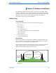
Tranzeo Wireless Technologies Appendix A Where to ground the device? This radio must be grounded at the pole and at the POE. This is because the radio is between the exterior antenna and the POE ground. See the examples below. Grounded Radio A grounded radio causes the surge to pass directly to ground, bypassing the radio. Ungrounded Radio An ungrounded radio causes the surge to pass through the radio. In this case, the radio most likely will be damaged. TR-49 Series Pitt Meadows, B.C.
Tranzeo Wireless Technologies Appendix A Grounded POE In this case, the surge will be picked up by the Cat 5 cable and since the POE is grounded, the route for the surge is through the POE to ground. Ungrounded POE In this case, the surge will be picked up by the Cat 5 cable and since the POE is not grounded, the route for the surge is through the radio to the antenna, and out through the building. TR-49 Series Pitt Meadows, B.C.
Tranzeo Wireless Technologies Appendix B Appendix B: Quality of Service Configuration (QoS) Tranzeo Wireless Technologies’ software ensures a consistently high quality online experience through the use of powerful Quality of Service (QoS) mechanisms. The key to making this applicable in a WISP environment is the Intelligent Stream Handling, a patent-pending algorithm that autonomously manages the flow of traffic going to the Internet without the need for user configuration.
Tranzeo Wireless Technologies Appendix B QoS Block Diagram Tranzeo software has the capability of continually monitoring and classifying traffic on the Internet connection, and dynamically adjusting the way individual streams are handled at any point in time. This enables latencysensitive traffic, such as voice, games or even web page requests, to be given a relatively high priority. As a result, they are sent to their destination first, reducing delay and jitter.
Tranzeo Wireless Technologies Appendix B Network QoS Example Internet Bandwidth Shaper In this case, no user is ever able to draw more than their fair share of the available up stream bandwidth, even if the communication is between two stations on the same access points. 30 MB 5A PxP 5A PxP In this case, the head end shaper is limiting the incoming demand based on the end user to ensure no user is taking the entire downstream.
Tranzeo Wireless Technologies Appendix C Appendix C: Protocol List Dec 0 1 2 3 4 5 6 7 8 9 10 11 12 13 14 15 16 17 18 19 20 21 22 23 24 25 26 27 28 29 30 31 32 33 34 35 36 37 38 39 40 41 42 43 44 45 46 47 48 49 50 Keyword HOPOPT ICMP IGMP GGP IP ST TCP CBT EGP IGP BRM NVP-II PUP ARGUS EMCON XNET CHAOS UDP MUX DCN-MEAS HMP PRM XNS-IDP TRUNK-1 TRUNK-2 LEAF-1 LEAF-2 RDP IRTP ISO-TP4 NETBLT MFE-NSP MERIT-INP SEP 3PC IDPR XTP DDP IDPR-CMTP TP++ IL IPv6 SDRP IPv6-Route IPv6-Frag IDRP RSVP GRE MHRP BNA ESP Pro
Tranzeo Wireless Technologies Appendix C Dec Keyword Protocol 101 102 103 104 105 106 107 108 109 110 111 112 113 114 115 116 117 118 119 120 IFMP PNNI PIM ARIS SCPS QNX A/N IPComp SNP Compaq-Peer IPX-in-IP VRRP PGM Ipsilon Flow Management PNNI over IP Protocol Independent Multicast ARIS SCPS QNX Active Networks IP Payload Compression Sitara Networks Protocol Compaq Peer Protocol IPX in IP Virtual Router Redundancy PGM Reliable Transport any 0-hop protocol Layer Two Tunneling Protocol D-II Data Excha
Tranzeo Wireless Technologies Appendix D Appendix D: Common TCP Ports Visit http://www.iana.org/assignments/port-numbers for a full list of well known port numbers. Keyword ECHO SYSTAT QOTD MSP FTP-DATA FTP TELNET SMTP NAME BOOTPS BOOTPC TFTP WWW KERBEROS POP3 NNTP NFS SIP TR-49 Series Pitt Meadows, B.C.
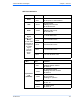
Tranzeo Wireless Technologies Appendix E Appendix E: Channel Allocations The TR-49 Series operates between 4940MHz and 4990MHz. It can operate on 5, 10, or 20MHz channels. Your channel use will be governed by your local co-ordination committee. 20MHz Channels Channel Center Frequency Channel Center Frequency # (GHz) # (GHz) 190 4.950 194 4.970 191 4.955 195 4.975 192 4.960 196 4.980 193 4.965 5MHz and 10MHz Channels Channel Center Frequency Channel Center Frequency # (GHz) # (GHz) 189 4.945 194 4.
Tranzeo Wireless Technologies Appendix F Appendix F: Wiring Standard TIA/EIA-568-B is a set of standards for cabling telecommunications products and services. Follow these standards, as described in the diagram below, to wire the Cat 5 cable during installation of the Tranzeo radio (see Step 3 in Chapter 2: Hardware Installation - Installing the Ethernet Cable). TR-49 Series Pitt Meadows, B.C.
Tranzeo Wireless Technologies Appendix G Appendix G: Routing Quick Start Guide What do you mean by a routable subnet? To many people, routing can be a black art. So many explanations of routing explain the binary logic behind it, but not how to actually use it. This document is designed to offer some practical advise on routing based on some of the common questions our customers ask us. It is not intended to be the definitive source of all routing info.
Tranzeo Wireless Technologies Appendix G So what is a Router? Note: The following is a super simple explanation of a router. Routers are like a bad boss, they either shout out information to anyone within earshot or they if don’t know what to do with the information, they pass the information on to someone else to deal with. This is commonly referred to as shouting or routing. Routers shout at the machines inside the network, and route the data addressed to machines located outside their network.
Tranzeo Wireless Technologies Appendix G Examples Connecting Multiple Clients to the Internet using NAT Assuming that you have a full Class C sub net (216.129.68.X), you have 254 possible IP’s to use, from 1 to 254. The Subnet mask for this can be written as 255.255.255.0 or /24. In order to connect clients to the Internet, you can make use of Private IP and NAT. Let’s keep it simple for now, and use some default values. The Tranzeo Radio uses the default IP address of 192.168.1.
Tranzeo Wireless Technologies Appendix G Public IP’s to less than 10 Clients Through One Radio Assuming that you have a full Class C sub net, 216.129.68.X, you have 254 possible IP’s to use, from 1 to 254. The Subnet mask for this can be written as 255.255.255.0 or /24. However, you want to give each client a public IP. If the client has only PC or a router to attach, then bridge mode will work fine. See example below.
Tranzeo Wireless Technologies Appendix G Public IP’s to multiple Clients Through One Radio Assuming that you have a full Class C sub net, 216.129.68.X, you have 254 possible IP’s to use, from 1 to 254. The Subnet mask for this can be written as 255.255.255.0 or /24. However, you want to give each client a public IP. If the client has less than 10 PC’s or an external router to attach, then bridge mode will work fine. See example above.
Tranzeo Wireless Technologies Appendix H Appendix H: PxP Install Checklist The following are some of the steps you should go through when planning a Point to Point (PxP) link. Step 1: Finding the Location • • • Determine the 2 endpoint locations. Calculate the distance between the locations. Find the heights of the locations Link Distance Free Space Loss Free space attenuation = 36.
Tranzeo Wireless Technologies Appendix I Appendix I: Glossary of Terms AP: Access Point ARP: Address Resolution Protocol CPE: Client Premise Equipment CTS: Clear To Send DFS: Dynamic Frequency Selection DHCP: Dynamic Host Configuration Protocol DNS: Domain Name Server DTIM: Delivery Traffic Indication Message EIRP: Effective Isotropic Radiated Power FTP: File Transport Protocol HTML: HyperText Markup Language HTTP: HyperText Transport Protocol IP: Internet Protocol ISP: Internet Service Provider LAN: Loca
Tranzeo Wireless Technologies Appendix J Appendix J: AutoConfig Autoconfig is a feature that allows you to apply configuration settings from a text file using a TFTP server or by using the radio's web server. The TFTP server address can be specified as a DHCP parameter using the "next server" parameter, or specified in the CPE's Configuration Settings page in the HTTP interface. The expected configuration filename is in the format .cfg.
Tranzeo Wireless Technologies Appendix J Example usage: 1. Configure typical CPE parameters for your network in an operational CPE . 2. Save the configuration and store it as a generic name. 3. Open the same configuration, and edit the parameters that will be different such as a. IP address b. Name c. Passwords 4. Save the edited file as .cfg.
Tranzeo Wireless Technologies Appendix J ii. Specify IP address of TFTP server (Optional if DHCP server specifies TFTP server in “next server”. Consult your DHCP Server’s documentation for more information about how to set this option) iii. Specify filename of configuration file. The file must be in the correct location for the TFTP server. Consult the TFTP server’s documentation for information about how to configure the TFTP server. iv.
Tranzeo Wireless Technologies Appendix J LEDs Arrange for Auto Configuration via TFTP D16 D17 D18 D19 D20 D15 D14 D13 Ethernet LED: Off: Ethernet link not established On: Ethernet link established Radio LED: Off: no radio card on the board On: a radio card on the board Power LED: Always blink in auto configuration mode Signal1 LED: Off: IP link not established Blink: sending DHCP request On: IP link established Signal2 LED: Off: TFTP connection not established Blink: connecting TFTP server On:
Tranzeo Wireless Technologies Appendix J # ************************** # Auto Configuration for TR6 # Version: 1.0.1 # Date: July 9, 2007 # Version: 1.0.2 # Date: January 29, 2009 # Version: 1.0.3 # Date: October 20, 2009 # Author: Patrick Ping Xu # ************************** # ----------------------------------------------------------------------------------# Format Instruction: # (There is no complete validation for the configuration in the firmware.
Tranzeo Wireless Technologies Appendix J # -------------------# admin. # -------------------admin.device_name = TR6Rt admin.admin_token = admin:default admin.super_token = recover:recover admin.led_enabled = Yes admin.snmp_read_community = public admin.snmp_sys_location = Location admin.snmp_sys_contact = Contact admin.snmp_traffic_format = Counter32 admin.block_locator_access = No admin.auto_config_enabled = No admin.auto_config_timeout = 60 admin.auto_config_server = 192.168.1.170 admin.
Tranzeo Wireless Technologies Appendix J net.router.nat_enabled = Yes # [Yes | No] # -------------------# net.router.route. # -------------------net.router.route.user_gateway_enabled = No net.router.route.user_gateway_interface = WAN net.router.route.user_gateway = 0.0.0.0 ; entries 0-7 net.router.route.interface.0 = None net.router.route.ip_address.0 = 0.0.0.0 net.router.route.subnet_mask.0 = 0.0.0.0 net.router.route.gateway.0 = 0.0.0.0 net.router.route.metric.
Tranzeo Wireless Technologies Appendix J net.router.dhcp_server.dns1 = 0.0.0.0 # [IP] net.router.dhcp_server.dns2 = 0.0.0.0 # [IP] net.router.dhcp_server.dns_relay_enabled = Yes # [Yes | No] net.router.dhcp_server.domain_use_wan_assigned = No # [Yes | No] net.router.dhcp_server.domain_name = localdomain # [STRING.59] net.router.dhcp_server.wins_use_wan_assigned = No # [Yes | No] net.router.dhcp_server.wins1 = 0.0.0.0 # [IP] net.router.dhcp_server.wins2 = 0.0.0.0 # [IP] # -------------------# net.router.
Tranzeo Wireless Technologies Appendix J wireless.country_code = US wireless.tx_rate = 0 wireless.tx_supported_rates = 0003 wireless.rts_threshold = 3000 wireless.beacon_period = 100 wireless.burst_time = 0 wireless.fragmentation_threshold = 2346 wireless.dot11d_enabled = No wireless.dot11h_mode = None wireless.invisibility = No wireless.dtim_interval = 1 wireless.wds_enabled = No wireless.wds_mac_address.0 = 000000000000 wireless.wds_mac_address.1 = 000000000000 wireless.wds_mac_address.
Tranzeo Wireless Technologies Appendix J wireless.security.radius_shared_secret = password wireless.security.radius_auth_mac = Yes # -------------------# wireless.access_control. # -------------------; it must be enabled before entry fields wireless.access_control.enabled = No ; entries 0-255 wireless.access_control.mac.0 = FFFFFFFFFFFF wireless.access_control.access.0 = Allow # [STRING.64] # [Yes | No] # [Yes | No] # [MAC] # [Allow | Deny] # -------------------# duplex.
Tranzeo Wireless Technologies Appendix K Appendix K: Tranzeo Electrical Plugs Electrical Plug Type Letter Description F FCC / North American adapter C ETSI / Euro adapter A FCC / Euro adapter U ETSI / UK adapter M FCC / UK adapter * * 24 volt version shown. TR-49 Series Pitt Meadows, B.C.
Tranzeo Wireless Technologies Appendix L Appendix L: Warranty Terms Effective Jan 1st, 2008 Warranty Period Summary for All Tranzeo Brand WiFi Units All Warranties now start from Day of Invoice Accessories All Power Supplies and POE Items Warranty Term 90 Days All Cables and Antennas 1 year Radios Sold Before May 1st, 06 1 year Sold Before Dec 1st, 06 Sold Before Jan 1st, 08 2 Years 3 Years Sold After Jan 1st, 08 3 Years Parts and Labor plus additional 2 years on Parts Warranty Terms 1.
Tranzeo Wireless Technologies Appendix K 4. Items Covered By A One Year Warranty The following Tranzeo Wireless manufactured products are warranted against defects in material and workmanship for a period of one year from date of Manufacture, under normal use: · All products sold prior to May 1st, 2006 · All TR-CPE200 products regardless of Sale Date · All Antennas · All Cables 5. Tranzeo Wireless manufactured products are covered by a Parts and Labor Depot Warranty.
Tranzeo Wireless Technologies Appendix K 11. The sole responsibility of Tranzeo Wireless Systems under this warranty shall be limited to repair of this product, or replacement thereof, at the sole discretion of Tranzeo Wireless Systems Special Warranty Terms For Customers in Canada, USA and the European Union . 12. All RMA items shipped to Tranzeo Wireless must be freight prepaid. Tranzeo Wireless will pay the return freight via a service of Tranzeo Wireless Technologies' choice.
Tranzeo Wireless Technologies Appendix K Who to Contact for an RMA? There are 3 ways to discuss any technical difficulties and request an RMA #: 1. Fill out our online RMA Request Form at http://support.tranzeo.com/rmarequest.php 2. Call our Technical Support Center via the local number listed at http://support.tranzeo.com 3. Or email our RMA Department at rma@tranzeo.com What information will be required? 1. Customer name/ID # and contact information 2.
Tranzeo Wireless Technologies Appendix K i. Repaired or replaced product will be subject to the original warranty period but not less than 90 days. j. All items must be shipped pre-paid. Tranzeo Wireless will not accept any collect packages. Tranzeo will pay the shipping to return your products. We recommend insuring the package using the values from our commercial invoice. k. Be sure to package the items well. Original packaging should be used for shipping.
Tranzeo Wireless Technologies Appendix K c) A returned product without clearly marked RMA # will be refused and returned to sender. How to ship? a) We recommend that you use a shipping service with tracking (i.e. UPS/FedEx ground) to ship your RMA. b) Products returned for warranty repair or out-of-warranty replacement, must be marked with a valid RMA number and shipped FOB Destination, Prepaid. c) Approximate turnaround time is 21 business days for warranty repairs and replacements.
Tranzeo Wireless Technologies Appendix K Shipping Firms do have legal obligations and limitations as to when and how much to compensate for damage, but only if the claim is filed on time and in the correct manner. You must file the claim as soon as possible. Making a Damage Claim If you receive a shipment that appears to have been damaged by the shipper during shipping, take the steps on the on the box then contact us so we have a record of the incident.
Tranzeo Wireless Technologies Appendix M Appendix M: How Can We Improve? Please take a moment to help us improve your experience with Tranzeo Wireless. Please fax the completed questionnaire to 604-460-6005. Each month we will draw for a free gift.
Tranzeo Wireless Technologies Appendix N Appendix N: Notes TR-49 Series Pitt Meadows, B.C.