
User's Manual


4
3.
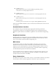
Auxilliary port 1:
RS232 serial interface port used for MDC programming and for
connection to external peripheral devices.
4.
Auxilliary port 2:
RS232 serial interface port for connection to external peripheral devices.
5.
Auxilliary port 3:
RS232 serial interface port for connection to external peripheral devices.
6.
Keyboard port:
Interface port for connection to the Express Mini QWERTY keyboard.
In the most basic MDC installation, only the vehicle and communications connectors will
to be required.
Communications Interface
The installation cable provided will bring the appropriate interface pins from the
communications connector to an appropriate adapter for the communications device.
Details for specific interfaces are available as application notes from Mentor Engineering,
Inc.
Peripherals Interface
Details regarding the cabling interface for external MDC peripheral devices, odometers,
and additional I/O are available as application notes specific to these functions. These
notes are provided as required by Mentor Engineering, Inc.
MDC Cables
In general, there will be one cable from the MDC connected to power (see Power
Connections section) and one cable connected to the communications device (radio,
modem, etc.). It is common practice to route the cabling through the vehicle so it is not
visible to the driver and is more protected from the environment. Mentor Engineering
recommends that this practice be followed in installations.
In some installations that use GPS, there will also be a GPS antenna that will have to be
mounted on the roof of the vehicle and connected to the MDC via the GPS connector
(usually located at the bottom of the MDC).
Power Connections
The MDC receives power via the vehicle connector. The installation cable that is provided
for the vehicle connector will have pigtails for connection to power and ground.