
Installation Guide


BBXHardwareInstallationGuide 1_3.doc
November 25, 2004
Page 9 of 16
Suite 230, 2891 Sunridge Way NE, Calgary Alberta, T1Y 7K7
♦ Phone: (403) 777-3760 ♦ Fax: (403) 777-3769
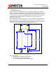
Power, Ignition Sense, Odometer and Vehicle I/O
4. 14pin Micro Fit Connector: (MOLEX43045-1406)
Radio I/O
5. USB-B Slave Port
6. Future Use
7. User Interface
LEDs to indicate – USB Good link, Error, In Coverage, Transmit Indicate,
GPS, Power (IGN on).
8. 8 position Modular Jack - RJ48 (AMP 406525-1)
RS232 Comm/Debug Port
3.2 Communications Interface (2 Way Radio)
The installation cable provided will bring the appropriate interface pins from the
communications connector to an appropriate adapter for the communications device
(i.e. mobile radio). Details for specific interfaces are available as application notes
from Mentor Engineering, Inc. See Interface Point #4 above.
3.3 Vehicle Interface
Details regarding the cabling interface for external BBX peripheral devices,
odometers, and additional I/O are available as application notes specific to these
functions. These notes are provided as required by Mentor Engineering, Inc. See
Interface Point #3 above.
4 Cabling
The BBX receives power via the Mentor supplied power cable (4-CAS-BBXVEHC075-00).
Power and Ignition Sense lines need to be installed with the in-line fuses provided. See
cable pin out for details.
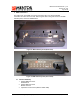
The BBX has a USB Slave Port located under the BBX cable cover. In order to fit the USB
cable under the BBX cable cover, a short over-mold USB cable must be used. This cable
is available in several lengths from Mentor.
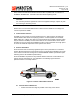
It is common practice to route the cabling through the vehicle so it is not visible to the
driver and is protected from the environment. Mentor Engineering recommends that this
practice be followed in all installations.
If an external device (i.e. mobile radio) is being used with the BBX the installation must
ensure that there is a common ground between the devices. BBX Power leads can be
crimped onto the power leads at the power input to the communications device. Installing
the power leads in this way will avoid the possibility of the ground potential at BBX
differing from the ground potential of the communications device (due to current draw
during a transmit cycle).
The BBX should be installed to unswitched power. The unit will use the ignition line to
power on and off automatically.
The in-line power fuse is a 3-amp MINI blade fuse (2-FUS-MINI003A-00). The power fuse
must be installed within 4” of the Vehicle Battery. The in-line ignition fuse is a 2-amp MINI
blade fuse (2-FUS-MINI002A-00). The Vehicle ignition line must be fused with the in-line
fuse provided or through the vehicle fuse box.