
User's Guide


Redpine Signals, Inc. Proprietary and confidential Page 6
RS9110
-
N
-
11
-
02
Evaluation
Board
User Guide
Version 1.41
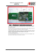
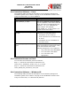
Figure 2: RS9110-N-11-02 Evaluation Board and Connectors
A probe point (Jumper PB9) is provided in order to measure the total power
consumed by the RS9110-N-11-02 WLAN Module during transmit, receive,
and standby modes.
On board resistors are provided for the Mode Select, which helps the user to
switch from the SDIO host interface to SPI host interface.
A SMD-based Microwave switch connector is provided to detach the onboard
antenna, and attach external RF input/output of any signal generator/signal
analyzer through a Microwave Cable Adapter (Murata Part
Number::MXHS83QH3000).
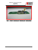
The following diagram illustrates how the user can connect an adapter with
Microwave coaxial cable to the switch connector.