OPERATING INSTRUCTIONS COVERS MODEL 41094 KC1803-R00 121206
WARNING! Carefully read and follow all instructions in this and any accompanying materials to prevent serious damage to your model. Failure to follow these instructions will be considered abuse and/or neglect. Introduction Fuel It’s imperative that you use the correct fuel in your Pro.15 engine for maximum performance and engine life. Traxxas Top Fuel® Power Plus™ should be used to ensure correct engine lubrication, performance, and ease of tuning. Thank you for purchasing the Traxxas Nitro Stampede.
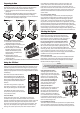
Fuel Bottle Fuel is usually purchased by the gallon or quart, so a smaller bottle with a dispensing tube is required to fill the fuel tank. The fuel tank in the Nitro Stampede has a capacity of 75cc. The fuel bottle should always be capped to prevent the fuel from evaporating and becoming contaminated with debris or moisture. The alcohol and nitro contents of the fuel will evaporate, thus upsetting the fuel balance and spoiling the fuel.
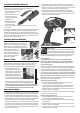
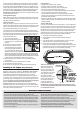
Installing Transmitter Batteries TUR N GH RI T TU RN Your TQ 2.4GHz transmitter uses 4 AA batteries. The battery compartment is located in the base of the transmitter. 1. Remove the battery compartment door by pressing the tab and lifting the door up. 2. Install the batteries in the correct orientation as indicated in the battery compartment. 3. Reinstall the battery compartment door and snap it closed. 4. Turn on the transmitter and check the status LED for a solid green light.
Warning: Changing the direction of the throttle servo will also change its neutral position. Be certain to confirm the throttle servo properly closes the engine’s throttle opening when the transmitter’s trigger is at neutral. Using the Radio System The TQ 2.4GHz Radio System has been adjusted at the factory for correct operation with your model. The adjustment should be checked before running the model, in case of movement during shipping. Follow these steps: 1. Turn the transmitter switch on.
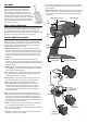
Preparing to Run Charging the EZ-Start® Battery The included charger can be used to charge the included battery pack. Do not leave the battery unattended while charging. 1. Plug the charger into the wall. The LED on the charger should glow green. 2. Connect the included EZ-Start battery pack to the charger output cord. The LED will glow red, indicating the battery is charging. 3. The battery should charge for approximately 4 ½ hours. The LED will turn green when the battery is fully charged.
and low throttle. This adjustment will smooth the idle and improve acceleration to mid-speed. Make this adjustment with the throttle closed, after setting the idle. Gently turn this screw clockwise until it stops against the needle seat. Be very careful. It’s difficult to know when the needle has seated due to the thread-holding material on the needle’s thread. Overtightening of the screw may result in damage to the needle seat. Now turn the low-speed mixture screw counterclockwise 1¾ turns.
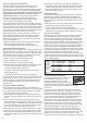
Tuning Your Engine for Best Performance The engine’s performance depends on the fuel mixture. Turn the mixture needles clockwise to lean the fuel mixture and counterclockwise to richen it. Leaning the fuel mixture will increase engine power up to the engine’s mechanical limits. Never run the engine too lean (not enough fuel flow). Leaning the engine beyond the safe allowable limits will result in poor performance and engine damage.
the engine performance does not change, then you have exceeded the maximum safe lean setting. If tuning for maximum performance results in engine temperature exceeding 300°F, try to increase airflow to the engine by cutting out the rear of the body, windshield, and front valance. If the engine temperature still cannot be kept in check, richen the high-speed needle slightly.
Centering your Servos Whenever your radio system has been removed for service or cleaning, the servos must be re-centered prior to installing the radio system in the model. If the radio system is installed in the truck, disconnect the servo horns from the servos. Connect the steering servo to channel 1 on your receiver and the throttle servo to channel 2. The white wire on each servo cable is positioned towards the center.
one to see if the problem goes away. You can view the glow plug element by removing it and touching it against the engine head while pressing the EZ-Start button. The glow plug will not light unless it is grounded against the engine. Glow plugs can be damaged by particles in the combustion chamber or by running the fuel mixture excessively lean. Traxxas makes three glow plugs. The standard hot plug (part #3230) is the stock replacement plug for Pro.15 engines.
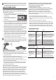
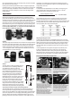
STEP 12: The piston and sleeve are a matched set. When the piston and sleeve are disassembled, they must be reassembled in the same orientation. Use a hobby knife to scratch a mark to indicate the location of the piston in relation to the pinning of the sleeve. STEP 11: Remove the backplate and the starter shaft. Replace the backplate gasket with a new one during assembly. STEP 5: Use a 2.5mm hex driver to remove the three remaining 3x10mm cap-head machine screws from the engine mount.
STEP 18: Remove the clutch bell gear and the clutch shoes. Note that there are two 5x8mm PTFE washers, one on each side of the clutch bell gear. Check the clutch shoes for excessive wear or cracking around the pin holes. If the clutch shoes are worn to the point that the clutch spring contacts the clutch bell, then the shoes must be replaced. STEP 17: It is not necessary to remove the clutch assembly unless you are servicing the clutch, crankshaft, or engine bearings.
STEP 33: Turn the gear over and install the other ball bearing. STEP 27: Place another drop of oil on the connecting rod bushing. Rotate the crankshaft several times to distribute the oil. STEP 30: Reinstall the starter shaft. Align the notch in the starter shaft with the crankshaft journal pin (arrow). STEP 29: Install new head gaskets on the head. Use one thick and one thin gasket. Reinstall the head using the 3x12mm cap-head machine screws.
NOTES: 15
FCC Compliance This device contains a module that complies with the limits for a Class B digital device as described in part 15 of the FCC rules. Operation is subject to the following two conditions: (1) This device may not cause harmful interference, and (2) this device must accept any interference received, including interference that may cause undesired operation. The limits for a Class B digital device are designed to provide reasonable protection against harmful interference in residential settings.