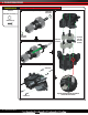
MODEL 82016-4 ASSEMBLY MANUAL
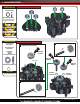
INTRODUCTION Thank you for purchasing the all-new Traxxas TRX-4 unassembled kit. The design of the TRX-4 instantly obsoletes the status quo with greatly expanded features and versatility. The TRX-4 features the powerful Titan® 21T 550 motor, waterproof electronics, and a smooth XL-5 HV 3s LiPo-capable electronic speed control. The game-changing portal axles provide greater ground clearance while the rigid steel frame eliminates chassis flex and allows you to navigate tough terrain. The new Canyon Trail 1.
INTRODUCTION RADIO SYSTEM INSTRUCTIONS The Traxxas TQi 2.4GHz radio system is provided with your unassembled kit. Complete instructions for operating the radio system are included in the TRX-4 Owner’s Manual. You can download the Owner’s Manual for the TRX-4, as well as the manuals for all Traxxas vehicles, at Traxxas.com.
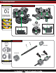
A. TRANSMISSION ASSEMBLY TRANSMISSION BAG A1. Insert 5x11x4mm bearings into transmission case halves Transmission Case Halves (2) 5x11x4mm BB (5) Note: Bearing Seating Press down hard to ensure bearings are fully seated. 3 7 7 Bearing installs on the outside of case half Side view Side view TRANSMISSION BAG A2. Assemble input shaft Input Shaft 2x9.
A. TRANSMISSION ASSEMBLY TRANSMISSION BAG A3. Assemble output shaft Output Shaft 24T Output Gear 24T output gear and drive hub assembly 5x8x2.5mm BB 36T output gear assembly 5x8x2.5mm BB Drive Hub Side view assembled 36T Output Gear 5x8x2.5mm BB 5x10x4mm BB Shift dog assembly 5x8x2.
A. TRANSMISSION ASSEMBLY TRANSMISSION BAG Shift Fork A4. Install input and output assemblies into main transmission housing 1 Place washers on output assembly 5x8x0.5mm PTFE Washer (2) 5x8x0.5mm PTFE Washer 3 Place assemblies into transmission case halves 2.5x8mm CS (5) 5x8x0.5mm PTFE Washer Input Gear Assembly 2 Place shift fork into shift dog recess 24T Output Gear and Drive Hub Assembly Shift Fork 4 Secure transmission case halves together 2.5x8mm CS 2.
A. TRANSMISSION ASSEMBLY TRANSMISSION BAG A5. Install bearings into the transfer case Transfer Case Cover 5x11x4mm BB (5) Note: Bearing Seating Press down hard to ensure bearings are fully seated. 3 7 7 TRANSMISSION BAG Long Transfer Case Output Shaft A6. Assemble and install transfer case gears 2 Short output shaft assembly 1 27T transfer case gear assembly Short Transfer Case Output Shaft 2x9.
A. TRANSMISSION ASSEMBLY TRANSMISSION BAG A7. Assemble transfer case Transfer Case Cover 2.5x8mm CS (3) 2.5x8mm CS Once assembled, turn input shaft. The gears should spin freely with no binding. TRANSMISSION BAG A8. Install slipper clutch and spur gear 45T Spur Gear Locknut 4x8 Metal Washer Spring Washer Spring washer orientation Slipper Plate Remove friction material backing and apply to spur gear Slipper Friction Material 2.0mm Hex Wrench To tighten the slipper nut, insert the 2.
A. TRANSMISSION ASSEMBLY TRANSMISSION BAG A9. Install shift linkage and high/low shift servo Transmission Servo Mount 2065 Hi/Low shift servo Shift Linkage 3x8mm BCS (4) ELECTRONICS BAG 2065 Servo Assembly 3x8mm BCS Note: Servo horn is pre-installed and factory-centered. Do not turn servo shaft by hand or you could damage the servo. 3x8mm BCS It is okay to slightly rock NO! horn to align ball cup. Do not turn servo shaft by hand or you could damage the servo.
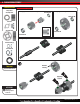
B. DIFFERENTIAL ASSEMBLY DIFFERENTIAL BAG B1. Install long output and spider gears into differential carrier Differential Carrier Spider gear assembly Spider Gear (4) Diff. Output Gear (Long) Crosspin (2) Crosspin Diff. Output Gear (Long) Differential Carrier x2 DIFFERENTIAL BAG Ring Gear 4 B2. Install ring gear assembly onto differential carrier 1 Apply a LARGE drop of grease between spider gears. 2 Diff. Output Gear (Short) Apply light coating Diff. Output Gear (Short) 2.
B. DIFFERENTIAL ASSEMBLY DIFFERENTIAL BAG B3. Install locking slider and bearings onto differential carrier assembly 2.5x12mm Pin 15x21x4mm BB 2.5x12mm Pin Locking Slider 7x14x5mm BB Locking Slider 15x21x4mm BB 10x15x4mm BB 7x14x5mm BB Pin will fit in slot of locking slider.
C. REAR AXLE ASSEMBLY REAR AXLE BAG C1. Insert bearings, pinion gear and differential assembly into axle housing Rear Axle Housing Apply drop of grease Differential Assembly 11T Pinion Gear 6x13x5mm BB Assembled 5x11x4mm BB 6x13x5mm BB 5x11x4mm BB TOOLS BAG High Performance Grease Differential assembly Apply drop of grease ACCESSORY Option Part 8297 Differential Spool REAR AXLE BAG Locking Cable Locking Fork 12 • TRAXXAS TRX-4 C2.
C. REAR AXLE ASSEMBLY REAR AXLE BAG C3. Install locking fork and locking cable 3mm E-Clip 1 Use needle nose pliers to set E-clip between locking cable and axle housing. 2 Use needle nose pliers to press E-clip onto locking cable. C4. Verify locking fork installation Move the end of the locking cable in and out to verify the locking fork moves back and forth on its pivot.
C. REAR AXLE ASSEMBLY REAR AXLE BAG C5. Install differential housing cover Differential Housing Cover 2.5x16mm CS (4) 2.5x16mm CS ACCESSORY Option Part 8280R Red Differential Cover 2.5x16mm CS Option Part 8280X Chrome Differential Cover REAR AXLE BAG C6. Install axle portal mounts to axle housing Axle Portal Mounts (2) 2.5x10mm CCS (6) 2.5x10mm CCS Note Orientation Note Orientation ACCESSORY Aluminum Accessory Portal Axle Adapter 14 • TRAXXAS TRX-4 2.
C. REAR AXLE ASSEMBLY REAR AXLE BAG C7. Insert bearings into portal housings Inner Rear Portal Housing Outer Rear Portal Housing 4x10mm BB 4x10x4mm BB 6x13x5mm BB 6x12x4mm BB 6x12x4mm BB 6x13x5mm BB x2 REAR AXLE BAG C8.
C. REAR AXLE ASSEMBLY REAR AXLE BAG 2.5x10mm CS (8) C9. Assemble portal housings Assembled 2.5x10mm CS 2.5x10mm CS REAR AXLE BAG C10. Install axle driveshafts 2.5x16mm CS (4) Right Axle Driveshaft (Long) Right Axle Driveshaft Left Axle Driveshaft Left Axle Driveshaft (Short) Right Axle Driveshaft 2.5x16mm CS Left Axle Driveshaft ACCESSORY Option Part 8061 Heavy Duty Rear Axles 16 • TRAXXAS TRX-4 2.
C. REAR AXLE ASSEMBLY REAR AXLE BAG C11. Install link mounts and 12mm wheel hexes 3x10mm Screw Pin Left Link Mount Right Link Mount Note Threads 2.5x10mm CS (4) 3x10mm Screw Pin (2) 12mm Wheel Hex 12mm Wheel Hex (2) 2.5x10mm CS Note Orientation ACCESSORY Aluminum Accessory Aluminum Wheel Hex Aluminum Accessory Aluminum Link Mounts Note Orientation 2.5x10mm CS Completed rear axle assembly Check your assembly carefully.
D. FRONT AXLE ASSEMBLY FRONT AXLE BAG D1. Insert bearings, pinion gear and differential assembly into axle housing Front Axle Housing Apply drop of grease Differential Assembly 11T Pinion Gear 6x13x5mm BB Assembled 5x11x4mm BB 6x13x5mm BB TOOLS BAG 5x11x4mm BB High Performance Grease Apply drop of grease Differential assembly ACCESSORY Option Part 8297 Differential Spool FRONT AXLE BAG Locking Cable Locking Fork 18 • TRAXXAS TRX-4 D2.
D. FRONT AXLE ASSEMBLY FRONT AXLE BAG D3. Install locking fork and locking cable 3mm E-Clip 1 Use needle nose pliers to set E-clip between locking cable and axle housing. 2 Use needle nose pliers to press E-clip onto locking cable. D4. Verify locking fork installation Move the end of the locking cable in and out to verify the locking fork moves back and forth on its pivot.
D. FRONT AXLE ASSEMBLY FRONT AXLE BAG D5. Install differential housing cover Differential Housing Cover 2.5x16mm CS (4) ACCESSORY 2.5x16mm CS Option Part 8280R Red Differential Cover Option Part 8280X Chrome Differential Cover FRONT AXLE BAG 2.5x16mm CS D6. Install caster blocks onto axle housing Left Caster Block 2.5x10 CCS Right Caster Block 2.5x10mm CCS (6) Note Orientation 2.5x10 CCS ACCESSORY Aluminum Accessory Caster Blocks FRONT AXLE BAG Note Orientation D7.
D. FRONT AXLE ASSEMBLY FRONT AXLE BAG D8. Assemble and install portal input and output gears Front Left Driveshaft 1 Left Driveshaft (Short) Portal input gear assembly Front Right Driveshaft 2x12mm Pin 2.5x4mm BCS (3) Right Driveshaft (Long) Portal Input Gear (Front) 2.5x10mm CS (8) Front Driveshaft 2x12mm Pin (2) 12x18x4mm BB CV Crosspin CV Crosspin 12x18x4mm BB 2 Note Orientation! Apply drop of grease Short drive shaft installs in left portal housing Portal Output Gear 2.5x4mm BCS 2.
D. FRONT AXLE ASSEMBLY FRONT AXLE BAG D9. Install portal/driveshaft assemblies to axle 3x12mm BCS (4) Portal Assembly Kingpin Bushing (4) Right Axle Driveshaft (Long) 3x12mm BCS Left Axle Driveshaft (Short) Left Axle Driveshaft (Short) 3x12mm BCS Kingpin Bushing Kingpin Bushing Right Axle Driveshaft (Long) 3x12mm BCS 3x12mm BCS FRONT AXLE BAG Portal Assembly D10. Install link mounts and 12mm wheel hexes Left Link Mount 3x10mm Screw Pin Right Link Mount 2.
D. FRONT AXLE ASSEMBLY FRONT AXLE BAG D11. Install steering link to portal housings 3x15mm BCS SUSPENSION LINK BAG Drag Link 3x15mm BCS Drag Link ACCESSORY Option Part 8274 Hollow Ball Set Drag Link 92.18mm 133.18mm Completed front axle assembly Check your assembly carefully.
E. CHASSIS ASSEMBLY CHASSIS PLASTICS BAG E1. Assemble front bumper mount crossmember, steering servo mount, and front fender to right chassis rail Right Chassis Rail Steering Servo Mount Front Bumper Mount Crossmember Steering Servo Mount Front Bumper Mount Crossmember Note Orientation Right Chassis Rail Right Front Fender Front View 3x10mm BCS (2) 3x12mm BCS (2) Right Front Fender 3x10mm BCS 3x12mm BCS ACCESSORY Option Part 8216 Shock Towers CHASSIS PLASTICS BAG E2.
E. CHASSIS ASSEMBLY CHASSIS PLASTICS BAG E3. Assemble front lower gear cover and center skidplate to chassis rail Lower Gear Cover Center Skidplate Rear Right Wire Clip 1 2 Lower Gear Cover Center Skidplate Lower Gear Cover 3 3x10mm BCS (2) 3x12mm BCS 3x10mm BCS Top view 3x10mm BCS Rear Right Wire Clip 3x12mm BCS CHASSIS PLASTICS BAG E4.
E. CHASSIS ASSEMBLY CHASSIS PLASTICS BAG E5. Assemble left chassis rail and left front fender to right chassis rail assembly Left Chassis Rail 3x8mm FCS Left Front Fender Front Battery Plate 3x10mm BCS (2) 3x10mm BCS 3x12mm BCS (2) Left Front Fender 3x8mm FCS (4) Left Chassis Rail 3x12mm BCS ACCESSORY Option Part 8216 Shock Towers CHASSIS PLASTICS BAG E6.
E. CHASSIS ASSEMBLY CHASSIS PLASTICS BAG E7. Assemble left rear fender to right chassis rail assembly and install rock light covers to fenders Left Rear Fender Rock Light Covers (8) 2.5x6mm CS (10) 2.5x6mm CS Rock Light Cover 3x10mm BCS 3x10mm BCS (4) 3x10mm BCS x8 3x12mm BCS 2.5x6mm CS 2.5x6mm CS 3x12mm BCS 2.5x6mm CS 2.5x6mm CS ACCESSORY Option Part 8026 Rock Light Kit Completed chassis assembly Check your assembly carefully.
F. ELECTRONICS INSTALLATION CHASSIS PLASTICS BAG F1. Install transmission assembly into chassis assembly Chassis Assembly 3x10mm BCS Transmission Assembly 3x10mm BCS (3) Place servo wire into clip before installing screws 3x10mm BCS ELECTRONICS BAG Upper Gear Cover Titan 550 Motor F2. Install motor into chassis assembly 1 Pinion gear should be 1-1.
F. ELECTRONICS INSTALLATION CHASSIS ELECTRONICS PLASTICS BAG BAG F3. Install lower receiver box onto chassis assembly Lower Receiver Box TQi 2.4GHz Receiver Receiver Foam Tape Receiver Foam Tape 3x6mm BCS (2) Place on smooth surface portion (note orientation) Front of model 3x6mm BCS 3x6mm BCS ELECTRONICS BAG CHASSIS PLASTICS BAG F4. Install steering servo onto chassis assembly 2075 Servo 3x10mm FCS 3x10mm FCS (4) Note Orientation: Servo wires exit on left side ELECTRONICS BAGBAG F5.
F. ELECTRONICS INSTALLATION ELECTRONICS BAG Chassis T-Lock Servo Mount 2065 Servo (2) F6. Install T-Lock servos onto chassis 1 3x8mm BCS 3x8mm BCS 3 Route wires from the ESC and the shift servo through the top loop of the T-Lock servo mount before installing the mount on the chassis. 3x8mm BCS (6) 4 Chassis T-Lock Servo Mount 3x8mm BCS Note servo arm orientation. Ball cup mounts should be on the same side as the top loop of servo mount. 2 Note wire routing ELECTRONICS BAG F7.
F. ELECTRONICS INSTALLATION ELECTRONICS BAG F9. Install wires into receiver box Correct wire routing Zip Tie Bundle excess wires in receiver box ELECTRONICS BAG 2.5x8mm CS (2) BATT/CH5 Rear T-Lock Servo CH4 Front T-Lock Servo CH3 Shift Servo CH2 Electronic Speed Control CH1 Steering Servo Caution! Pinch point for wires. F10.
F. ELECTRONICS INSTALLATION CHASSIS PLASTICS BAG F11. Assemble and install battery tray Battery Tray 3x10mm CCS Battery Hold-down Pivot Post 3x10mm BCS (2) 3x12mm BCS (2) Pivot Post Screw Battery Clip Battery Hold-down Battery Clip Pivot Post 3x12mm BCS Screw Pin Battery Hold-down Screw Pin Battery Tray 3x10mm CCS (2) ELECTRONICS BAG Steering Servo Horn Pivot Post Screw 3x10mm BCS F12. Center the steering servo 1 3x12mm BCS F13.
G. SUSPENSION & DRIVELINE INSTALLATION DAMPER BAG G1. Assemble GTS shocks x4 Shock Assemblies Silicone Shock Oil 1 2 Front Shock Springs Rear Shock Springs Upper Spring Retainers Unscrew cap Fill with shock oil 3 4 5 Slowly move piston to remove excess air Lower Spring Retainers 6.35mm (.25") Note: Shaft should be fully compressed when cap is installed. Add oil to reach the proper level Exercise shock to make sure it compresses fully. If it does not, it is overfilled.
G. SUSPENSION & DRIVELINE INSTALLATION SUSPENSION LINK BAG G2. Attach front shocks and front lower suspension links to front axle assembly 3x27mm BCS (2) Front Lower Suspension Links Left Front Shock Assembly 3x27mm BCS Front Axle Assembly Right Front Shock Assembly ACCESSORY Option Part 8140 Lift Kit 8140X Lift Kit Option Part 8274 Hollow Ball Set SUSPENSION LINK BAG Front Lower Suspension Links 3x27mm BCS 75.78mm Front Lower Suspension Link 114.78mm G3.
G. SUSPENSION & DRIVELINE INSTALLATION SUSPENSION LINK BAG G4.
G. SUSPENSION & DRIVELINE INSTALLATION SUSPENSION LINK BAG 3x27mm BCS (2) 3x30mm BCS G5.
G. SUSPENSION & DRIVELINE INSTALLATION SUSPENSION LINK BAG G6.
G. SUSPENSION & DRIVELINE INSTALLATION SUSPENSION LINK BAG 2.6x8mm BCS (2) G7. Attach ball cups to differential locking cables 1 2 Differential Cable Axle Ball Cup (2) Screw ball cup on until all threads are hidden Axle Ball Cup 3 4 2.6x8mm BCS It is okay to slightly rock horn to align ball cup. Do not turn servo shaft by hand or you could damage the servo. NO! SAFE 2.6x8mm BCS NO! DRIVELINE BAG 3x6mm BCS (4) G8.
G. SUSPENSION & DRIVELINE INSTALLATION DRIVELINE BAG G9. Install front and rear driveshafts 3x10mm Screw Pin (4) Front driveshaft installation 3x10mm Screw Pin 3x10mm Screw Pin Rear driveshaft installation 3x10mm Screw Pin 3x10mm Screw Pin Completed suspension & driveline installation Check your assembly carefully.
H. FINAL CHASSIS ASSEMBLY SUSPENSION LINK BAG M4x0.7 NL (4) H1. Assemble wheels and tires; install on front and rear axles x2 x2 Wheels (4) Tires with Foam Inserts (4) Traxxas Ultra Premium Tire Glue (Part #6468 Sold Separately) x4 ACCESSORY Option Part Wheel and tire options available. See parts list. Glue the tires to the wheels. Use your thumb to push the side of the tire away from the wheel. Repeat at four points around the wheel. Turn the wheel over and repeat on the inside of the wheel.
H. FINAL CHASSIS ASSEMBLY BODY ACCESSORIES BAG H3. Install front and rear body mounts Front Body Mount (Short) Rear Body Mount (Long) 3x18mm Screw Pin (4) Front Body Mount (Short) Rear Body Mount (Long) 3x18mm Screw Pin 3x18mm Screw Pin Adjust the body mount height as necessary to fit the body you choose for your new TRX-4. (Wheel wells may need to be trimmed for body to fit.) BODY ACCESSORIES BAG H4.
H. FINAL CHASSIS ASSEMBLY BODY ACCESSORIES BAG H5.
SAFETY PRECAUTIONS WARNING! CAUTION! DANGER! FIRE HAZARD! Your model is able to use LiPo batteries. Charging and discharging batteries has the potential for fire, explosion, serious injury, and property damage if not performed per the instructions. Before use, read and follow all manufacturer’s instructions, warnings, and precautions.
SAFETY PRECAUTIONS All of us at Traxxas want you to safely enjoy your new model. Operate your model sensibly and with care, and it will be exciting, safe, and fun for you and those around you. Failure to operate your model in a safe and responsible manner may result in property damage and serious injury. The precautions outlined in this manual should be strictly followed to help ensure safe operation. You alone must see that the instructions are followed and the precautions are adhered to.
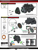
QUICK START GUIDE The following guide is an overview of the procedures for getting your model running. The complete manual for your model can be viewed and downloaded by following the link on the cover of this manual or by scanning the QR code. Please read this entire manual for complete instructions on the proper use and maintenance of your model. Read the Safety Precautions For your own safety, understand where carelessness and misuse could lead to personal injury and product damage.
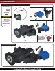
QUICK START GUIDE Operating Your Model Unlock Diffs TU R N R HT IG TUR N LE Lock Front Diff Lock Both Diffs FT Switch forward = both differentials locked. Maximum climbing ability and traction. Reduced steering performance. On surfaces with good traction, it is normal for the truck to appear to alternately bind and slip the tires when attempting tight turns with the differentials fully locked.
QUICK START GUIDE Selecting a Throttle Mode: SPORT, RACE, TRAINING, TRAIL, OR CRAWL 1. Connect fully charged batteries to the model and turn on your transmitter. 2. With the model off, press and hold the EZ-Set button until the LED turns solid green, then solid red, and then begins blinking red. It will blink once, then twice, then three times, then repeat. One blink = Sport Mode is the default setting. It allows full forward and reverse throttle.
ASSEMBLY MANUAL MODEL 82016-4 6250 TRAXXAS WAY, McKINNEY, TEXAS 75070 1-888-TRAXXAS 180228 KC2560-R01