
Owner manual


MAXIM 50E/U PUMP OPERATION / MAINTENANCE MANUAL PAGE 5
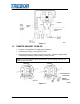
1.3 PROBE ASSEMBLY INSTALLATION (E MODEL ONLY)
Optic Cable: 1mm core; 1/4” PFA protective tubing.
Install seal into head.
Install probe assembly into head.
Thread probe cap into head hand tight only, no tool needed.
Connect fiber optic cable to sensor. NOTE: Minimize bends in fiber optic
cable to 2” radius minimum to help ensure optimum signal strength. NOTE:
Standard cable length is 15 ft. [4.57 meters].
Figure 1-2
1.4 PLC CONTROL SCHEMATIC
Shown below is an example of the fiber optic end of stroke detection for a Maxim
Pump. The Programmable Logic Controller (PLC) control schematic shown will
allow the Maxim to be controlled by a PLC. Some of the features that can be
programmed are:
Start and stop pump
Monitoring approximate flow rate
Leak sensing
High and low flow rate detection
Preventative maintenance counter
Cycle counting
Oscillator control override
NOTE: See examples of ladder logic programs in Section 4.10.