Phone: 800-669-1303 or 801-561-0303 Fax: 801-255-2312 e-mail: treborservice@idexcorp.com MAGNUM 620R PUMP Operation / Maintenance Manual SERIAL NUMBER (located on back of product): PATENTS: U.S. 09642426, U.S. 06106246, U.S. 05971402, U.S.
CONTENTS 1 2 3 4 5 6 7 INSTALLATION ............................................................................................................ 3 1.1 UNPACKING ...................................................................................................... 3 1.2 UTILITIES / HOOK-UP ....................................................................................... 3 1.3 CHECK MUFFLER OPERATION ....................................................................... 5 1.3.a Purpose ............
1 INSTALLATION 1.1 UNPACKING After unpacking, the pump should be checked for any damage that may have occurred during shipment. Damage should be reported to the carrier immediately. The following items should be included within the shipping container: Qty 1 1 1.2 Item 620 M620R Description Magnum 620 Pump Operation/Maintenance Manual UTILITIES / HOOK-UP It is recommended that the pump be positioned within 15 from level to maintain self-priming ability and pumping efficiency.
Figure 1-1: Dimensional Views ATTENTION: The pump should be operated with clean, dry air or nitrogen. Particulate, water and oils in the air supply can damage the pump. NOTE: 1. It is recommended that a filter be placed on the discharge side of the pump. 2. Although extensive efforts are made to deliver pumps to our customers completely dry, new pumps may contain residual moisture from their final DI water test.
1.3 CHECK MUFFLER OPERATION 1.3.a Purpose NOTE: The check muffler is not designed to control pump speed. Use of the check muffler for this purpose could result in serious damage to the pump. Permits pump to operate reliably in systems that incorporate a discharge flow less than 3 gpm. Permits pump to operate reliably in systems that have the pump located at an elevation below the liquid supply level and flows below 3 gpm. (Pump air supply remains on.
If none of the aforementioned conditions exist when operating the pump, then the final setting of the check muffler may be used. To obtain maximum flow capability and lowest start pressure (<10 psi), completely remove the spring assembly from the check muffler assembly. This is the recommended condition to obtain best performance and life from the pump. Most normal open recirculation applications may be operated successfully under this condition.
1.4 REMOTE EXHAUST HOOK-UP Some installations may benefit from remotely exhausting air from the pump to eliminate unwanted air turbulence or to prevent potentially damaging chemical vapors from entering the pump air cavities. Remove existing Muffler Assembly from the back of pump head. Install Exhaust Plug in Exhaust Port. Install the appropriately sized (3/8” OD) fitting and tubing (not provided) to remote exhaust.
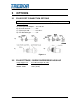
2 OPTIONS 2.1 FLUID PORT CONNECTION OPTIONS NOTE 1: Use O-ring to seal stainless steel or other rigid plumbing. Available Options A) Flare style tube adapter….1/2” and 3/4" B) PFA tube stub out………...3/4" C) Pillar Super 300…………..3/4” OR 1” D) PFA Weldable pipe……….3/4" A) B) C) D) Figure 2-1 2.2 FLUID FITTINGS / SURGE SUPPRESSOR HOOK-UP Surge Suppressor MODEL SS40 MODEL SS85 PAGE 8 Assembled Height: IN (CM) 12.63 (32.08) 14.97 (38.
Figure 2-2 NOTE: See Surge Suppressor Operation Manual for detailed installation instructions.
3 START-UP Pump air supply pressure must be regulated. (See Figure 3-3: Pressure vs. Fluid Temperature Chart.) Open the fluid suction (IN) line valve, if necessary. Open the fluid discharge (OUT) line valve, if necessary. Start slowly with air regulator at low (> 20 psi) pressure setting. Increase pressure to attain desired flow, up to the maximum rating (See Section 3.1). Table 1: Consumption / Efficiency can be used to determine approximate air consumption.
Discharge Pressure (psi) 90 Medium Load* 80 No Spring Load Required 70 60 50 40 30 20 10 0 0 2 4 6 8 10 12 Flow (gpm) * Switch to high load setting if pump experiences positive inlet condition. Figure 3-1: Flow Performance NOTE: Test information is based on specific conditions and limited sampling. Use for general reference only.
Flow (gpm) No Load 10 Medium Load 8 High Load 6 4 30 40 50 60 70 80 Supply Pressure (psig) Figure 3-2: Flow Comparison @ Various Loads Maximum Supply Pressure (PSIG) 90 80 70 60 50 40 30 20 10 0 0 10 20 30 40 50 60 70 80 90 100 110 Fluid Temperature (Celsius) MTD0485 Figure 3-3: Pressure vs. Fluid Temperature Chart Recommended Maximum Pump Operating Levels NOTE: Be sure that fittings and tubing used are capable of these operating conditions.
4 MAINTENANCE Trebor pump maintenance can be divided into two categories: air system maintenance and fluid system maintenance. The purpose of air system maintenance is to prevent air system failures such as stalling or erratic cycling. The purpose of fluid system maintenance is to maintain suction and lift capabilities. Pump Rebuild Service Trebor International provides a factory rebuild service for customers using Trebor products. Trebor will rebuild any standard pump (exclusive of options).
24 Months 21 Months 18 Months 15 Months 12 Months 9 Months 6 Months 3 Months 30 Days Install MAGNUM 620R Maintenance Schedule R R R Poppet Pilot Valves and Seats C-Ring and Detent Legs Muffler Media Shaft Seal and Shaft Check Balls and O-Rings Diaphragms Check Plug Seal Suction and Discharge Check Cage R R R R I I=Inspect, R=Replace PAGE 14 MAGNUM 620R PUMP OPERATION / MAINTENANCE MANUAL
4.1.
4.
4.
4.
Immerse or flush the pump assembly using DI water and a neutralizing agent. Install mounting fittings in pump adapter ports and lock body into bench mounting fixture. NOTE: Securely attach mounting fixture to work surface using hardware provided. Figure 4-1 Remove transfer tubes and fittings from pump head. Figure 4-2 Using a strap wrench, turn heads counter-clockwise to remove. Remove head and check diaphragms for cracks or cuts.
CAUTION: Following disassembly, parts should be thoroughly washed and free from chemical residue for handling purposes. 4.7.a Body Disassembly Remove (2 each) check plugs and seal on top of pump body using 3/4” pin tool. Remove discharge sleeve using sleeve removal tool. Remove PTFE ball and O-ring. Remove suction sleeve using sleeve removal tool. Remove second set of O-rings and balls.
Tilt the detent ring (item 3) over one of the legs, and align the groove on the inside of the detent ring with the end of the detent leg. Tilt the other side of the ring down, expanding it slightly, so that the other detent leg snaps into the detent ring groove. See Fig. 3. The completed assembly should look like Fig. 4 (see Figure 4-3). Figure 4-3 Insert spool assembly into shuttle sleeve (do not lubricate spool or sleeve). Install seal onto seal groove shoulder of shuttle cap.
ATTENTION: Threads should be snug. Do not over tighten. Thread muffler assembly into head using 3/4” pin tool. 4.8.b Pump Assembly NOTE: Check sleeves that fit too tightly for easy installation should be placed in a freezer prior to assembly to assist insertion. Body must be upside down with check port extending over a table edge so that parts remain assembled during insertion of sleeves. (See Figure 4-5.) Figure 4-5 Insert suction sleeve, check ball and O-ring carefully into check bore.
Install two shaft seals in shaft bore groove with slits 180 apart. Thread shaft into push plate until engagement with the shaft shoulder is achieved. Additionally apply a ¼” turn to ensure proper installation. Insert shaft through shaft bore using shaft bullet as shown (This prevents damage to the TFE shaft seals and prevents dislodgement of shaft seals). Figure 4-6 Remove shaft insert tool and thread second push plate until engagement with the shaft shoulder is achieved.
Figure 4-7 Install fittings and transfer tubes. See Figure 4-8. Reconnect both air supply and fluid lines.
4.
5 TROUBLESHOOTING Pump Will Not Start, Fails to Operate Cause: Insufficient air pressure. Insufficient air volume (low supply pressure during running). Fluid discharge line blocked. Downstream valve closed, filter plugged or other obstruction. Pilot valve failure. Detent failure. Solution: Must be minimum 12 psig at pump air hook-up. If check muffler spring assembly is installed at high setting, start pressure may be up to 35 psi. See Performance Charts (3.1) for requirements.
6 WARRANTY MAGNUM 620 PUMP TREBOR International, Inc. warrants to the purchaser of new equipment manufactured by TREBOR to be free from defects in material and workmanship when used for its intended purpose under normal operating conditions, and maintained according to the Operation/Maintenance Manual.
7 CONTACT INFORMATION 7.1 GENERAL CONTACT INFORMATION Web: www.treborintl.com Phone Number: (801) 561-0303 Toll Free Number: (800) 669-1303 Fax Number: (801) 255-2312 7.2 7.3 Email: treborinfo@idexcorp.com treborsales@idexcorp.com Address: Trebor International 8100 South 1300 West West Jordan, Utah 84088 U.S.A. TECHNICAL SUPPORT Email: treborservice@idexcorp.com Phone Number: (801) 244-6156 REGIONAL REPRESENTATIVES Web: PAGE 28 http://www.treborintl.com/about_contact_us.