Phone: 800-669-1303 or 801-561-0303 Fax: 801-255-2312 e-mail: treborservice@idexcorp.com PC7 PUMP CONTROLLER Operation / Maintenance Manual SERIAL NUMBER (located on top of product): PATENTS: U.S. 09642426, U.S. 06106246, U.S. 05971402, U.S.
CONTENTS 1 5 INSTALLATION............................................................................................................3 1.1 UNPACKING ......................................................................................................3 1.2 UTILITIES / HOOK-UP .......................................................................................3 OPTIONS ......................................................................................................................5 2.
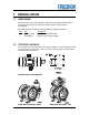
1 INSTALLATION 1.1 UNPACKING After unpacking, the pump should be checked for any damage that may have occurred during shipment. Damage should be reported to the carrier immediately. The following items should be included within the shipping container: Qty 1 1 1.2 Item PC7F or PC7P PC7-Manual Description PC7 PUMP CONTROLLER Manual, PC7 Pump Controller UTILITIES / HOOK-UP The controller can be mounted by any of three methods.
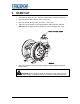
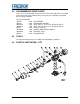
HEAD 1 CONNECTION AIR INLET CONNECTION HEAD 2 CONNECTION SPEED ADJUSTMENT SCREW MTD0619 Air Inlet: 3/8” Flaretek (3/8” OD TUBING) Air Supply: 20-80 PSIG (1.4 – 5.4 BAR), CLEAN DRY AIR OR NITROGEN. Head Ports: 3/8” Flaretek (3/8” OD PFA TUBING) Recommended Maximum Operating Levels: 80 psig (5.4 bar) ATTENTION: The controller should be operated with clean, dry air or nitrogen. Particulate, water and oils in the air supply can damage the controller.
2 OPTIONS 2.1 UNIT IS AVAILABLE IN BOTH PFA AND PP CONSTRUCTION The PFA unit exterior parts are molded using PFA (Fluoroplastic) and the shuttle assembly is constructed of PEEK & PPS. The PFA unit is intended for severe applications and for compliance with FM4910. The PP unit exterior parts are molded using Polypropylene (Polyolefin) and the shuttle assembly is constructed of PEEK & PPS. This unit is intended as a lower cost option with similar service life where exposure to oxidizing acids is limited.
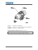
3 START-UP • Controller air supply pressure must be regulated to a maximum of 80 psig. • Open the fluid suction (IN) line valve, if necessary. • Open the fluid discharge (OUT) line valve, if necessary. • Adjust the speed control screw fully Clockwise (CW) until fully retracted. Warning! Do not apply too much torque to screw or damage may result. SPEED CONTROL SCREW MTD0629 • Open air supply line to operate pump. Operate pump at 20 psig initially to prime pump.
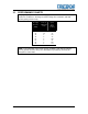
3.1 PERFORMANCE CHARTS Pumping capacity is a function of air supply pressure and volume, suction head, suction line restrictions, discharge head, discharge line restriction, and fluid specific gravity and viscosity. Air Supply Pressure Turns on adjustment screw Cycles Per Minute (+/-15%) 0 1/2 0 2 0 2 0 2 80 30 135 70 190 80 240 110 (PSIG) 20 20 40 40 60 60 80 80 NOTE: Test information is based on specific conditions and limited sampling. Use for general reference only.
4 MAINTENANCE 4.1 PREVENTIVE MAINTENANCE SCHEDULE The following maintenance schedule is recommended to optimize pump performance and minimize failures. Adhering to the recommended preventative maintenance schedule along with periodic inspection of the pump will ensure continued efficient operation and overall reliable pump performance. It is recommended that the Preventive Maintenance Record (Section 4.1.a) be copied, maintained and kept with this unit for future reference.
4.1.
4.2 RECOMMENDED SPARE PARTS There are no recommended spare parts for the Purus 20 pump due to it’s welded and sealed construction. However there are spare parts available for rebuild of the PC7 pump controller. PC7 Pump Controller 305-PD 4 EA 305-QA 2 EA 305-P016 2 EA 305-P015 2 EA 305-PJ 1 EA 305-P040 1 EA 305-P048 1 EA 305-FR 5 EA 4.3 LEG, DETENT SPRING BAR, DETENT SEAL, PTFE, 1.75 X 1.33 X .02 (PC7F ONLY!) SEAL, PTFE, 1.82 X 1.33 X .
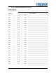
4.5 ILL NO PARTS LIST – PC7F PART NO QTY DESCRIPTION NUT, COMPRESSION,PVDF, 3/8 FERRULE, PTFE, PC7 CAP,PFA,ADJUST,PC7 SCR, ADJUST,PC7 LEG,DETENT,PC7 SPRING BAR,DETENT,OSCILLATOR PLATE,SUPPORT,PC7 SCR,NYLON,#8-32x.31,SLOVHD SPOOL,SHUTTLE,OSCILLATOR SEAL,PTFE,GORTEX,1.75x1.33x.02 RING,SPLIT,SINGLE TURN,PTFE,016 FTG,PVDF,3/8" ME ASSY,SHUTTLE SLEEVE TUBE,TRANSFER,PFA NUT,PVDF,FLR,3/8T BODY,OSCILLATOR,PFA,PC7 ORIFICE, PRESS-IN .
4.7 CLEAN-UP Due to possible contamination all components must be flushed clean and neutralized before disassembly to prevent fluid contact with personnel. 4.8 DISASSEMBLY To disassemble PC7 pump controller for service, remove controller from pump by disconnecting the flare fittings on the PC7 from the transfer tubes connecting it to the pump. Caution: For safety make sure air supply to PC7 has been shut off prior to removal of supply line. 4.
• Lastly insert 2 ea. detent legs into slots on shuttle spool as shown in Figure 3 and insert into previous assembly. MTD0632 Figure 3 • See completed detent assembly illustrated in Figure 4. MTD0633 Figure 4 • Insert detent assembly into adjustable cap as shown here and install 2 each retaining screws. MTD0634 Figure 5 Note: Do not over tighten screws. Cap threads are easily stripped. • Install ferrule onto adjustment screw with the longest taper toward the adjustment cap.
• Tighten nut finger tight to engage compression seal. • Insert Gortex seal into thread end of adjustable cap assembly onto sealing land as shown. MTD0636 Figure 7 • Screw cap assembly with seal onto the open end of body assembly carefully inserting shuttle spool into valve body and engage air seal completely. • Cap requires only moderate installation torque to activate seal. Over tightening can dislocate seal gasket preventing oscillation of the controller valve.
5 TROUBLESHOOTING Controller Will Not Operate or Cycles Erratically Cause: Solution: • PC7 cap seal failure • Remove caps from PC7 and replace PTFE cap seal. • Debris in shuttle valve • Isopropyl alcohol clean the shuttle sleeve and spool assy. • Insuffisant air pressure • • Adjustment Screw Seal failure • Increase regulated supply pressure or check control valves for proper operation. Rotate PC7 speed control screw CW until it stops. Then readjust for correct speed.
6 WARRANTY PC7F OR PC7P CONTROLLER TREBOR International, Inc. warrants to the purchaser of new equipment manufactured by TREBOR to be free from defects in material and workmanship when used for its intended purpose under normal operating conditions, and maintained according to the Operation/Maintenance Manual.