Phone: 800-669-1303 or 801-561-0303 Fax: 801-255-2312 e-mail: treborservice@idexcorp.com SS95 Surge Suppressor Operation / Maintenance Manual SERIAL NUMBER (located on top of product): PATENTS: U.S.
CONTENTS 1 2 3 INSTALLATION............................................................................................................3 1.1 UNPACKING ......................................................................................................3 1.2 LOCATING / MOUNTING SURGE.....................................................................3 1.2.a Port Mounted .........................................................................................4 1.2.b Inline, Internal Ports................
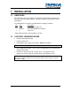
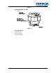
1 INSTALLATION 1.1 UNPACKING After unpacking, the Surge Suppressor should be checked for any damage that may have occurred during shipment. Damage should be reported to the carrier immediately. The following items should be included within the shipping container: Qty 1 1 1 Item SS95 MSS95 ** Description SS95 Surge Suppressor Operation/Maintenance Manual Seal, Port **Dependent upon type of pump option selected. 1.2 LOCATING / MOUNTING SURGE • Remove port plug from pump. • Install new port seal.
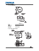
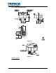
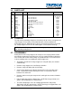
1.2.a Port Mounted 8.30 (21.08) AIR SUPPLY CONNECTION 3/8" TUBE REMOTE EXHAUST CONNECTION 1/8" TUBE 8.00 (20.32) 5.47 (13.89) IN (CM) MTD0375 Figure 1-1 Pump MEGA 960 MAXIM 25 MAXIM 50 Assembled Height: IN (CM) 15.06 (38.25) 12.22 (31.04) 13.97 (35.48) 1.2.b Inline, Internal Ports AIR SUPPLY CONNECTION 3/8" TUBE 8.00 (20.32) FLUID PORT FITTINGS (INCLUDED WITH TEE OPTION) REMOTE EXHAUST CONNECTION 1/8" TUBE CL 7.11 (18.06) 2.06 (5.23) 4.47 (11.35) 4.20 (10.67) 2.75 (6.99) 2.28 (5.79) 1.21 (3.
Figure 1-2 Assembled Height: IN (CM) 7.11 (18.
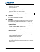
1.2.c Inline, External Ports AIR SUPPLY CONNECTION 3/8" TUBE 8.00 (20.32) REMOTE EXHAUST CONNECTION 1/8" TUBE CL 6.94 (17.63) 3/4" FLARE 1.64 (4.17) 4.47 (11.35) 1.21 (3.07) 4.20 (10.67) 3.75 (9.53) 2.75 (6.99) IN (CM) 2.46 (6.
2 MAINTENANCE 2.1 PREVENTIVE MAINTENANCE SCHEDULE SS95 Surge Suppressor 2 Year 1 Year Inspection 6 Month 4 Year 2 Year 1 Year Replacement X X X X 2.2 Component / Comments Poppet Pilot Valves and Seats Diaphragms Union Nut Retorque RECOMMENDED SPARE PARTS KRSS95-00-A Spares Rebuild Kit, which includes: Part No 1700C0047 98002450 AK020 AK030 AL023 2.3 Qty 1 1 1 1 1 Description Diaphragm O-ring Pilot Poppet Pilot Seal Pilot Seat Qty 1 1 1 1 1 Description Torque Wrench, 30-150 Ft. Lb.
2.
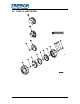
2.5 PARTS LIST ILL NO PART NO QTY DESCRIPTION 1 AL003-01 1 Union Nut 2 2a 3 3a 3b 3c 4 5 6 7 8 9 10 11 12 13 AM084 L0163 AL026 AL027 AL039 AL038 1700C0047 J0093 AL019 AL014 AL001 98002450 AL023 AK020 AK030 AL004 1 1 1 1 1 1 1 1 1 1 1 1 1 1 1 1 Seal,1.380x.63x.02 Seal,1.75x1.00x.02 Body, Maxim to SS95 Body, 960 to SS95 Body, Inline Connection. External Body, Inline Connection, Internal Diaphragm Push Plate Support Plate Shaft Head O-Ring Pilot Seat Pilot Poppet Pilot Cap Seal Pilot Cap 2.
• Remove support plate from head. • Remove push plate from shaft. • Remove head from vice. • Remove pilot cap and seal from head using 3/4” Pin Tool. • Remove pilot poppet from head. • Remove pilot seat from head using 3/4” Pin Tool. NOTE: Following disassembly, parts should be thoroughly washed and be free from chemical residue for handling purposes. 2.8 CLEANING Gently spray clean or tank rinse all components with DI Water to remove any trace of materials remaining after disassembly. 2.
3 WARRANTY SS95 SURGE SUPPRESSOR TREBOR International, Inc. warrants to the purchaser of new equipment manufactured by TREBOR to be free from defects in material and workmanship when used for its intended purpose under normal operating conditions, and maintained according to the Operation/Maintenance Manual.