
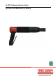
Operators Manual


MAINTENANCE
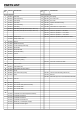
A vacuum shroud is available (See parts list for shroud
and cuff) which fits over the front tube. Position the front
of the cuff with the needle tips 15-20mm inside, adjust as
the needles wear. Tighten the caphead screw to secure.
Use a Trelawny recommended vacuum for 99.9% dust
containment.
Assembly
Ensure all parts are clean and internal parts have a film of
recommended lubricant.
Replace any parts that show signs of wear.
If the tool is being fully serviced, it is strongly
recommended to change all O’Rings (2), (5), (14), (18),
(25), (27), cushion ring (19), seals (13,) (29), ball valve
(17) and Needle Holder during assembly.
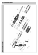
Valve assembly
Replacement of the Valve Body onto the Cover assembly
is the reverse of removal. Use a few turns of P.T.F.E.
tape on the threads of the handle and screw on the Valve
Body initially by hand, then insert the Valve Body in a
vice, holding securely on the flats provided, and with the
Cover (10) uppermost. Finally tighten up clockwise by
hand, holding the Front Tube and Cover, and align the
Throttle Lever with the front of the tool when resistance is
felt. Replace the O’Ring (2) on the Valve Cap (1). Fit a
new Valve seat O’Ring (5) in the Valve Body (6).Insert the
Valve Stem (4), in the Valve Body (6). Place the Valve
Spring (3) on top of the Valve Stem (4),screw down the
Valve Cap (1) by hand, and then fasten until fully tight
with a flat blade screwdriver.
Locate Throttle Lever (7) in the Valve Body (6) using a 3
mm punch to align holes.
Secure by inserting Spring Pin (8).
Tool assembly
Ensure that all components are clean and lubricated with
a thin film of the recommended lubricating oil. Assembly
is the reverse of dismantling.
Secure the Cover (10) vertically in a vice using the flats
provided, insert the Cylinder Guide Plate ensuring that
the flat face is uppermost, ensure that it is located onto
the shoulder at the bottom of the threaded section inside
the Cover. Fit the Cylinder stem into the bore of the
Cylinder Guide Plate. With the removal holes uppermost
carefully slide the Intermediate Tube over the Cylinder,
screwing down by hand. Finally tighten by using a 6mm
bar x 200mm through the holes provided. (Do not over
tighten). Gently insert the Piston, small diameter first into
the Intermediate Tube, if resistance is felt, turn the piston
slightly until it is located in the cylinder.
Note: When removing tool from vice, do not point the
front of the tool downward; the piston will fall out of the
tube and become damaged. Remove the tool from the
vice and follow as per Re-fitting the Needles, hold the tool
horizontal when completing this operation.
Disposal
Dismantle into component form, segregate according to
material composition and dispose of using waste
recycling processes specified by local regulations.
Cylinder Ball Valve replacement
This is a consumable item and will require replacing after
approximately 120 -160 hours use; this is dependant on
the cleanliness of the air supply and frequency of
lubrication.
Do not replace this plastic ball with a steel version, as
it will damage the cylinder valve seat and piston valve pin.
Remove the ball retaining O’Ring (18) from its groove just
inside the bore of the stem using a suitable pointed
implement. Remove the ball from the bore, replace and
refit new O’Ring into groove.
Piston Valve Pin replacement
Hold the piston in a vice by the stem, using a pair of pliers
break off the valve pin, use a 6mm drill & bit and remove
the remainder from the piston. A small socket (4mm)
which just fits over the actual pin, will stop damage
occurring. Drive the valve pin in up to its shoulder using a
vice or a small hammer.
Valve Body - Valve Stem removal
Hold the Valve Body (6) in a vice using the flats provided.
Using a 3 mm diameter punch, drive the Throttle Lever
retaining Spring Pin (8) out of the Valve Body (6) and
withdraw the Throttle Lever (7). Remove the Valve Cap
with O’Ring (2), Valve Spring (3), Valve Stem (4) and the
Valve Seat O’Ring (5).
Valve Body removal
Remove the Front Tube and remove Needle Holder,
Needles and Return Spring as per instructions for Needle
replacement above. Replace the Front Tube without the
Needles etc, onto the Intermediate Tube and screw up
until hand tight. Hold the Valve Body flats securely in a
vice, with the Cover (10) uppermost. Turn the tool anti-
clockwise around the Valve Body by holding the Cover
and Front Tube, unscrew the Valve Body from the handle
until loose, remove from vice and finally unscrew by hand.
Fitting of Chisel Holder
The Chisel Holder assembly comprises of an Anvil,
Spring, Chisel Holder and the Chisel. Unscrew Needle
Holder attachment and remove the assembly complete
with the needles etc, take care not to allow the internal
components to fall out of the intermediate tube. Separate
the Needle holder assembly and remove the spring. To fit
the Chisel Holder, first fit the spring onto the Anvil locating
against the large shoulder. Fit this assembly into the
intermediate tube and locate the large flat face of the
Anvil against the front face of the piston. Ensure that the
pinch bolt on the Chisel Holder is loose and screw the
Chisel Holder fully on to the intermediate tube. Then
unscrew slightly to position the boss underneath the tool
and tighten the pinch bolt using a 6mm AF Allen key.
Turn the knurled collar on the Chisel Holder until the
retaining ball is fully visible; insert the Chisel aligning the
rebate with the ball. Position the middle of the rebate on
the shank of the Chisel with the retaining ball and turn the
collar half a turn to lock the Chisel in place. To release
the Chisel, rotate the knurled collar until the retaining ball
is fully visible and remove the Chisel.