NX Variable Speed Drives Installation Manual Issue 3/A
Author: RTW/VACON Issue: 3/A Date: 04/07/2006 Part Number: TG200434 Copyright: Trend Control Systems Limited Horsham, W. Sussex All rights reserved. This manual contains proprietary information that is protected by copyright. No part of this manual may be reproduced, transcribed, stored in a retrieval system, translated into any language or computer language, or transmitted in any form whatsoever without the prior consent of the publisher.
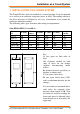
Contents CONTENTS 1 2 2.1 2.2 TREND NX DRIVES................................................................... 3 INSTALLATION ON A TREND SYSTEM................................. 5 Connections................................................................................ 7 2.1.1 Basic Connections ......................................................... 7 2.1.2 Using NXNI or NXIP interfaces...................................... 8 Sample Applications .......................................................
Contents This page is intentionally left blank 2 NX Variable Speed Drives Installation Manual TG200434 Issue 3/A 04/07/2006
Trend NX Drives 1 TREND NX DRIVES Trend Supply the following range of NX Variable Speed Drives All Trend NX drives have the following options: Nominal mains voltage 380 to 500 Vac 3 phase supply; alphanumeric keypad fitted; 6 pulse connection, air cooled, 2 standard boards (Basic I/O Board OPTA1, Basic Relay Board OPTA2). 3.
Trend NX Drives Part 3, 4, 5 of this manual are produced by VACON as follows: Part 3: VACON NX User’s Manual (vd00701s) (for VACON NX APPLICATION MANUAL referred to on the contents page, see NX Drives Application Manual TE200443, VACON NX Frequency Converters ‘All in One’ APPLICATION MANUAL, ud885f). Part 4: NX Basic Application from section 1 of NX Drives Application Manual TE200443, (VACON NX Frequency Converters ‘All in One’ APPLICATION MANUAL, ud885f).
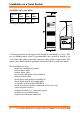
Installation on a Trend System 2 INSTALLATION ON A TREND SYSTEM The Trend NX drive must be installed in a vertical position. It can be mounted on a wall or in an enclosure using four screws or bolts. The cooling airflow to the drive must not be blocked in any way; recirculation of air inside the enclosure should be avoided.
Installation on a Trend System Size FR10 (385 A and 460 A) Current (A) 385 to 400 H1 (mm) W1 (mm) D1 (mm) 2275 600 600 3 Cooling air required: 2600 m /h Overload protection of the supply cable should be considered (e.g. fuses). The use of shielded motor cables is recommended; they should be routed as far away from other cables as possible, and cross other cables at right angles. The motor cable shield should be grounded at both the NX drive and at the motor.
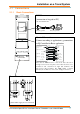
Installation on a Trend System 2.1 2.1.1 Connections Basic Connections RS232 (connection to keypad or PC) cable ACC/NX/RS2432PC 9Way D type Male 9Way D type Female Control Connections Connect according to application e.
Installation on a Trend System 2.1.2 Using NXNI or NXIP interfaces Trend NXNI or NXIP NXNI T- T+ R- R+ NXIP RJ45 Connector 100 m (109 yds) RJ45 Connector IQ System current loop connection Ethernet hub/switch The NXNI (NX network interface) or NXIP (NX Ethernet interface) can be fitted inside the NX drive to provide an IQ System network connection.
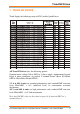
Installation on a Trend System Sensors Sensor Label ($) Units (%) Description 1 O-P Motor Speed rpm Operating motor speed 2 O-P Power kW kW Operating power to motor 3 O-P Frequency Hz Operating frequency to motor 4 O-P Current Amps Operating current to motor 5 Motor Torque % Percentage of rated drive torque 6 O-P Supply Voltage VAC Operating voltage to motor 7 Unit Internl Tmp degC 8 Min Frequency Hz 9 Max Frequency Hz 10 Preset Freq 1 Hz Internal drive temperature Mi
Installation on a Trend System Knobs Knob Label ($) 1 Demand 2* Failure Demand Units (%) % Top (T) 100 - 0 Limit Bottom (B) 0 Limit Description Defines required speed in terms of percentage of frequency range between minimum and maximum frequency (S8 to S9) Defines required speed if the watchdog strategy detects that the demand value has not been received.
Installation on a Trend System Plotting Channels Channel Sensor 1 S2 Label O-P Power kW 2 S3 O-P Frequency 3 S4 O-P Current Full details of the NXNI are provided in the NXNI Data Sheet, TA200544. Its installation is covered in the NXNI Installation Instructions, TG200543. Full details of the NXIP are provided in the NXIP Data Sheet, TA200826. Its installation is covered in the NXIP Installation Instructions, TG200827.
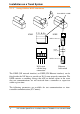
Installation on a Trend System 2.2 Sample Applications 2.2.1 NX drive - stand alone In this application the NX drive is supplied with 3 phase via a fuse and an isolating contact. An alternative is to use a fused switch (shown dotted). The start/stop contact connects terminals 6 to 8 to start the drive. The speed is set by the voltage signal at terminals 2, 3. The motor local isolator has an early break, late make contact in the circuit between terminals 6 and 8.
Installation on a Trend System 2.2.2 NX drive stand alone with start/stop contactor This application is similar to the previous, but now there is a start/stop contactor which stops the drive by both isolating the supply to the drive, and breaking the connection between terminals 6 and 8 (via contacts C1). The isolating switch will isolate both the drive and the start/stop contactor.
Installation on a Trend System 2.2.3 NX drive with Direct On line bypass In this application the drive can be bypassed. An Emergency Stop (ES) contact has been added in series with the start/stop contact which will disconnect the C1 coil, and isolate the drive, and switch it off via the C1 contacts. The bypass is operated by a 3 position switch (NX, Off, Bypass). In the NX position, the time delay contactor, T1, will cause C2 to operate.
Installation on a Trend System 2.2.4 NX drive with parallel motor operations In this application, the drive operates 2 motors which are separately isolated by two local isolators (L1 and L2). Since the NX drive is supplying both motors in parallel it cannot individually protect them, so each drive has an in-built thermistor relay which will operate if the motor overheats. TH1 will deenergise C1, and TH2 will de-energise C2.
Installation on a Trend System 2.2.5 NX drive with duty/standby motors This system drives 2 motors in duty/standby e.g. they are both mounted on a common drive shaft. The motors are controlled by a three position switch (Motor 1, Off, Motor 2). If Motor 1 is selected, then closing the start contact will energise the C1 coil which will connect terminals 6 and 8 together, and connect the output of the drive to motor 1.
2 • vacon AT LEAST THE 10 FOLLOWING STEPS OF THE START-UP QUICK GUIDE MUST BE PERFORMED DURING THE INSTALLATION AND COMMISSIONING. IF ANY PROBLEMS OCCUR, PLEASE CONTACT YOUR LOCAL DISTRIBUTOR. Start-up Quick Guide 1. Check that the delivery corresponds to your order, see Chapter 1. 2. Before taking any commissioning actions read carefully the safety instructions in Chapter 1. 3.
vacon • 3 CONTENTS VACON NXS/P USER’S MANUAL INDEX 1 SAFETY 2 EU DIRECTIVE 3 RECEIPT OF DELIVERY 4 TECHNICAL DATA 5 INSTALLATION 6 CABLING AND CONNECTIONS 7 CONTROL KEYPAD 8 COMMISSIONING 9 FAULT TRACING 24-hour support +358 (0)40 837 1150 • Email: vacon@vacon.
4 • vacon ABOUT THE VACON NXS/P USER'S MANUAL Congratulations for choosing the Smooth Control provided by Vacon NX Frequency Converters! The User's Manual will provide you with the necessary information about the installation, commissioning and operation of Vacon NX Frequency Converters. We recommend that you carefully study these instructions before powering up the frequency converter for the first time. This manual is available in both paper and electronic editions.
vacon • 5 Vacon NXS/P User's Manual Index Document code: ud00701S Date: 7.12.2005 1. 1.1 1.2 1.3 1.4 2. SAFETY ............................................................................................................................... 7 Warnings ..........................................................................................................................................7 Safety instructions ...................................................................................................
6 • vacon 6.1.5 Installation instructions ....................................................................................................49 6.1.5.1 Stripping lengths of motor and mains cables ...........................................................50 6.1.5.2 Vacon NX frames and installation of cables..............................................................51 6.1.6 Cable selection and unit installation in accordance with the UL standards..................59 6.1.
SAFETY 1. vacon • 7 SAFETY ONLY A COMPETENT ELECTRICIAN MAY CARRY OUT THE ELECTRICAL INSTALLATION 1.1 Warnings 1 2 3 4 5 WARNING 6 7 8 9 1.2 The Vacon NX frequency converter is meant for fixed installations only. Do not perform any measurements when the frequency converter is connected to the mains. Do not perform any voltage withstand tests on any part of Vacon NX. There is a certain procedure according to which the tests shall be performed. Ignoring this procedure may result in damaged product.
8 • vacon 1.3 SAFETY Earthing and earth fault protection The Vacon NX frequency converter must always be earthed with an earthing conductor connected to the earthing terminal . The earth fault protection inside the frequency converter protects only the converter itself against earth faults in the motor or the motor cable. It is not intended for personal safety. Due to the high capacitive currents present in the frequency converter, fault current protective switches may not function properly. 1.
EU DIRECTIVE 2. EU DIRECTIVE 2.1 CE marking vacon • 9 The CE marking on the product guarantees the free movement of the product within the EEA (European Economic Area). Vacon NX frequency converters carry the CE label as a proof of compliance with the Low Voltage Directive (LVD) and the Electro Magnetic Compatibility (EMC). The company SGS FIMKO has acted as the Competent Body. 2.2 2.2.
10 • vacon EU DIRECTIVE Class T: The T-class converters have a smaller earth leakage current and are intended to be used with IT supplies only. If they are used with other supplies no EMC requirements are complied with. Class N: The drives of this class do not provide EMC emission protection. This kind of drives are mounted in enclosures. External EMC filtering is usually required to fulfil the EMC emission requirements.
EU DIRECTIVE vacon • 11 EU DECLARATION OF CONFORMITY We Manufacturer's name: Vacon Oyj Manufacturer's address: P.O.Box 25 Runsorintie 7 FIN-65381 Vaasa Finland hereby declare that the product Product name: Vacon NXS/P Frequency converter Model designation: Vacon NXS/P 0003 5…. to 0520 5….
12 • vacon EU DIRECTIVE EU DECLARATION OF CONFORMITY We Manufacturer's name: Vacon Oyj Manufacturer's address: P.O.Box 25 Runsorintie 7 FIN-65381 Vaasa Finland hereby declare that the product Product name: Vacon NXS/P Frequency converter Model designation: Vacon NXS/P 0004 6…. to 0416 6….
vacon • 13 EU DECLARATION OF CONFORMITY We Manufacturer's name: Vacon Oyj Manufacturer's address: P.O.Box 25 Runsorintie 7 FIN-65381 Vaasa Finland hereby declare that the product Product name: Vacon NXS/P Frequency converter Model designation: Vacon NXS/P 0004 2…. to 0300 2….
14 • vacon 3. RECEIPT OF DELIVERY RECEIPT OF DELIVERY Vacon NX frequency converters have undergone scrupulous tests and quality checks at the factory before they are delivered to the customer. However, after unpacking the product, check that no signs of transport damages are to be found on the product and that the delivery is complete (compare the type designation of the product to the code below, Figure 3-1.
RECEIPT OF DELIVERY 3.2 vacon • 15 Storage If the frequency converter is to be kept in store before use make sure that the ambient conditions are acceptable: Storing temperature Relative humidity –40…+70°C <95%, no condensation If the storage time exceeds 12 months the electrolytic DC capacitors need to be charged with caution. Therefore, such a long storage time is not recommended. 3.3 Maintenance In normal conditions, Vacon NX frequency converters are maintenance-free.
16 • vacon TECHNICAL DATA 4. TECHNICAL DATA 4.1 Introduction Figure 4-1 presents the block diagram of the Vacon NX frequency converter. The frequency converter mechanically consists of two units, the Power Unit and the Control Unit. Pictures of the mechanical assemblage on pages 51 to 58.
TECHNICAL DATA vacon • 17 The control keypad constitutes a link between the user and the frequency converter. The control keypad is used for parameter setting, reading status data and giving control commands. It is detachable and can be operated externally and connected via a cable to the frequency converter. Instead of the control keypad, also a PC can be used to control the frequency converter if connected through a similar cable.
18 • vacon 4.2 TECHNICAL DATA Power ratings 4.2.1 Vacon NX_5 – Mains voltage 380—500 V High overload = Max current IS, 2 sec/20 sec, 150% overloadability, 1 min/10 min Following continuous operation at rated output current, 150 % rated output current (IH) for 1 min, followed by a period of load current less than rated current, and of such duration that the r.m.
TECHNICAL DATA 4.2.2 vacon • 19 Vacon NX_6 – Mains voltage 525—690 V High overload = Max current IS, 2 sec/20 sec, 150% overloadability, 1 min/10 min Following continuous operation at rated output current, 150 % rated output current (IH) for 1 min, followed by a period of load current less than rated current, and of such duration that the r.m.
20 • vacon 4.2.3 TECHNICAL DATA Vacon NX_2 – Mains voltage 208—240 V High overload = Max current IS, 2 sec/20 sec, 150% overloadability, 1 min/10 min Following continuous operation at rated output current, 150 % rated output current (IH) for 1 min, followed by a period of load current less than rated current, and of such duration that the r.m.
TECHNICAL DATA 4.3 vacon • 21 Brake resistor ratings Mains voltage 380-500 V, 50/60 Hz, 3~ NX 0003 5 Max. brake current [I] 12 Resistor nom [ohm] 63 NX 0105 5 Max. brake current [I] 111 Resistor nom. [ohm] 6.5 NX 0004 5 12 NX 0005 5 12 63 NX 0140 5 222 3.3 63 NX 0168 5 222 3.3 NX 0007 5 NX 0009 5 12 63 NX 0205 5 222 3.3 12 63 NX 0261 5 222 3.3 NX 0012 5 12 63 NX 0300 5 222 3.
22 • vacon TECHNICAL DATA Mains voltage 208-240 V, 50/60 Hz, 3~ NX 0004 2 Max. brake current [I] 15 Resistor nom [ohm] 30 NX 0061 2 Max. brake current [I] 46 Resistor nom. [ohm] 10 NX 0007 2 15 30 NX 0075 2 148 3.3 NX 0008 2 15 NX 0011 2 15 30 NX 0088 2 148 3.3 30 NX 0114 2 148 NX 0012 2 3.3 15 30 NX 0140 2 296 1.4 NX 0017 2 15 30 NX 0170 2 296 1.4 NX 0025 2 15 30 NX 0205 2 296 1.4 Converter type Converter type NX 0031 2 23 20 NX 0261 2 296 1.
TECHNICAL DATA 4.4 vacon • 23 Technical data Mains connection Motor connection Control characteristics Input voltage Uin Input frequency Connection to mains Starting delay Output voltage Continuous output current Starting current Output frequency Frequency resolution Control method Switching frequency (see parameter 2.6.
24 • vacon TECHNICAL DATA EMC (at default settings) Safety Immunity Emissions Control connections (apply to boards OPT-A1, OPT-A2 and OPT-A3) Analogue input voltage Analogue input current Digital inputs (6) Auxiliary voltage Output reference voltage Analogue output Digital outputs Relay outputs Protections Overvoltage trip limit Undervoltage trip limit Earth fault protection Mains supervision Motor phase supervision Overcurrent protection Unit overtemperature protection Motor overload protection Moto
INSTALLATION 5. INSTALLATION 5.1 Mounting vacon • 25 The frequency converter can be mounted in either vertical or horizontal position on the wall or on the back plane of a cubicle. However, if the drive is mounted in a horizontal position, it is not protected against vertically falling drops of water. Enough space shall be reserved around the frequency converter in order to ensure a sufficient cooling, see Figure 5-11, Table 5-10 and Table 5-11. Also see to that the mounting plane is relatively even.
26 • vacon INSTALLATION Ø W2 D1 H1 H2 H3 W1 E1Ø E2Ø* Ø fr5ip21.fh8 Figure 5-1.
INSTALLATION vacon • 27 W2 H4 D1 H5 D2 H1 H2 H3 W1 Ø fr5ip21kaulus.fh8 Figure 5-2. Vacon NX dimensions, FR4 to FR6; Flange mounting Type 0004—0012 NX_2 0003—0012 NX_5 0017—0031 NX_2 0016—0031 NX_5 0048—0061 NX_2 0038—0061 NX_5 0004—0034 NX_6 W1 W2 H1 Dimensions [mm] H2 H3 H4 H5 D1 D2 ∅ 128 113 337 325 327 30 22 190 77 7 144 120 434 420 419 36 18 214 100 7 195 170 560 549 558 30 20 237 106 6.5 Table 5-2.
28 • vacon INSTALLATION H2 Ø W3 W2 W1 H4 H1 H3 fr6aukko.fh8 Figure 5-3. The opening needed for the flange mounting, FR4 to FR6 Type 0004—0012 NX_2 0003—0012 NX_5 0017—0031 NX_2 0016—0031 NX_5 0048—0061 NX_2 0038—0061 NX_5 0004—0034 NX_6 Dimensions [mm] W3 H1 H2 H3 H4 ∅ – 5 6.5 420 – 5 6.5 549 7 5 6.5 W1 W2 123 113 – 315 325 135 120 – 410 185 170 157 539 Table 5-3. Dimensions for the opening for flange mounting, FR4 to FR6 5 Tel.
INSTALLATION vacon • 29 H7 W4 W2 H6 D1 H4 D2 H3 H1 H2 H4 W3 W1 H5 fr7kaulusip21.fh8 Figure 5-4. Vacon NX dimensions, FR7 and FR8, flange mounting Type 0075—0114 NX_2 0072—0105 NX_5 0041—0052 NX_6 0140—0205 NX_2 0140—0205 NX_5 0062—0100 NX_6 W1 W2 W3 W4 H1 Dimensions [mm] H2 H3 H4 237 175 270 253 652 632 630 188.5 289 - 355 330 832* – 759 258 H5 H6 H7 D1 D2 ∅ 188.5 23 20 257 117 5.5 265 57 344 110 9 43 Table 5-4.
30 • vacon INSTALLATION H2 H5 H2 H4 H3 H6 H1 W1 W2 W3 Ø fr7aukko.fh8 Figure 5-5. The opening needed for the flange mounting, FR7 Type 0075—0114 NX_2 0072—0105 NX_5 0041—0052 NX_6 W1 W2 W3 H1 233 175 253 619 Dimensions [mm] H2 H3 188.5 188.5 H4 H5 H6 ∅ 34.5 32 7 5.5 Table 5-5. Dimensions for the opening for flange mounting, FR7 Bottom edge of the opening H4 H3 H1 H1 H2 Figure 5-6.
INSTALLATION vacon • 31 Ø D1 D2 H4 H6 H3 W4 W1 W3 fr9ip21.fh8 H2 H5 H1 D3 Figure 5-7. The dimensions Vacon NX, FR9 Type W1 W2 W3 W4 0261—0300 NX_2 0261—0300 NX_5 480 400 165 0125—0208 NX_6 9 W5 H1 Dimensions [mm] H2 H3 H4 54 1150* 1120 H5 721 205 16 H6 D1 D2 D3 ∅ 188 362 340 285 21 Table 5-7. The dimensions Vacon NX, FR9 *Brake resistor terminal box (H6) not included, see page 56. 24-hour support +358 (0)40 837 1150 • Email: vacon@vacon.
32 • vacon INSTALLATION Ø D1 D2 D3 H4 H2 H4 H7 W5 W1 H3 H5 H3 H3 H5 W4 Opening W3 W2 W4 fr9collar.fh8 H1 H6 Figure 5-8. Vacon NX dimensions. FR9 flange mounting Type 0261-0300 NX_2 0261-0300 NX_5 0125-0208 NX_6 W1 W2 W3 W4 W5 H1 530 510 485 200 5.5 1312 Dimensions [mm] H2 H3 H4 H5 1150 420 100 35 H6 H7 D1 D2 D3 ∅ 9 2 362 340 109 21 Table 5-8. Vacon NX dimensions. FR9 flange-mounted 5 Tel.
INSTALLATION vacon • 33 W4 Type plate W2 W3 W1 Warning plate Figure 5-9. Vacon NX dimensions, FR10 and FR11 (floorstanding units) Type Dimensions [mm] W1 W2 W3 W4 H1 H2 H3 0385…0520 NX_5 595 291 131 15 2018 1900 0261…0416 NX_6 0590…0730 NX_5 794 390 230 15 2018 1900 0460…0590 NX_6 H4 H5 D1 1435 512 40 602 1435 512 40 602 Table 5-9. Vacon NX dimensions, FR10 and FR11 (floorstanding units) 24-hour support +358 (0)40 837 1150 • Email: vacon@vacon.
34 • vacon INSTALLATION Ty pe plate Y 15 Detail Y, 1:5 X Warning plate Detail X, 1:5 1197 Figure 5-10. Vacon NX dimensions, FR12 (floorstanding units) 5 Tel.
INSTALLATION 5.2 vacon • 35 Cooling Enough free space shall be left around the frequency converter to ensure sufficient air circulation, cooling as well as maintenance. You will find the required dimensions for free space in the tables below. If several units are mounted above each other the required free space equals C + D (see figure below). Moreover, the outlet air used for cooling by the lower unit must be directed away from the air intake of the upper unit.
36 • vacon INSTALLATION Cooling air required [m3/h) Type 0004—0012 NX_2 0003—0012 NX_5 0017—0031 NX_2 0016—0031 NX_5 0004—0013 NX_6 0048—0061 NX_2 0038—0061 NX_5 0018—0034 NX_6 0075—0114 NX_2 0072—0105 NX_5 0041—0052 NX_6 0140—0205 NX_2 0140—0205 NX_5 0062—0100 NX_6 0261—0300 NX_2 0261—0300 NX_5 0125—0208 NX_6 70 190 425 425 650 1300 Table 5-11. Required cooling air 5.2.2 Standalone units (FR10 to FR12) Mounting space dimensions [mm] B A B C 800 200 20 Table 5-12.
INSTALLATION 5.3 vacon • 37 Power losses 5.3.1 Power losses as function of switching frequency If the operator wants to raise the switching frequency of the drive for some reason (typically e.g. in order to reduce the motor noise), this inevitably affects the power losses and cooling requirements according to the graphs below.
38 • vacon INSTALLATION 1400,00 1200,00 1000,00 P [W] 800,00 600,00 400,00 200,00 0,00 0,00 2,00 4,00 6,00 8,00 10,00 12,00 14,00 16,00 Switching frequency [kHz] 0038NX5 400V 0061NX5 400V 0038NX5 500V 0061NX5 500V 0045NX5 400V 0045NX5 500V Figure 5-15.
INSTALLATION vacon • 39 4000,00 3500,00 3000,00 P[W] 2500,00 2000,00 1500,00 1000,00 500,00 0,00 0,00 2,00 4,00 6,00 8,00 10,00 12,00 Switching frequency [kHz] 0140NX5 400V 0140NX5 500V 0168NX5 400V 0168NX5 500V 0205NX5 400V 0205NX5 500V Figure 5-17.
40 • vacon INSTALLATION 8000,00 7000,00 6000,00 P[W] 5000,00 0385NX 400V 4000,00 0385NX 500V 0460NX 400V 0460NX 500V 0520NX 400V 3000,00 0520NX 500V 2000,00 1000,00 0,00 1 2 3 4 Switching frequency [kHz] Figure 5-19. Power loss as function of switching frequency; 0385…0520 NX_5 6 Tel.
CABLING AND CONNECTIONS vacon • 41 6. CABLING AND CONNECTIONS 6.1 Power unit 6.1.1 Power connections 6.1.1.1 Mains and motor cables The mains cables are connected to terminals L1, L2 and L3 and the motor cables to terminals marked with U, V and W. A cable entry gland should be used when installing the motor cable at both ends in order to reach the EMC levels. See Table 6-1 for the cable recommmendations for different EMC levels. Use cables with heat resistance of at least +70°C.
42 • vacon CABLING AND CONNECTIONS 4 = Screened cable equipped with compact low-impedance shield (NKCABLES /JAMAK, SAB/ÖZCuY-O or similar). Note: The EMC requirements are fulfilled at factory defaults of switching frequencies (all frames). 6.1.1.2 DC supply and brake resistor cables Vacon frequency converters are equipped with terminals for the DC supply and an optional external brake resistor. These terminals are marked with B–, B+/R+ and R–.
CABLING AND CONNECTIONS 6.1.1.5 vacon • 43 Cable and fuse sizes, NX_6, FR6 to FR9 The table below shows typical cable sizes and types that can be used with the converter. The final selection should be made according to local regulations, cable installation conditions and cable specification. IL [A] Fuse [A] Mains and motor cable Cu [mm2] NX0004 6—0007 6 3—7 10 3*2.5+2.5 NX0010 6—0013 6 10-13 16 3*2.5+2.
44 • vacon 6.1.1.7 CABLING AND CONNECTIONS Cable and fuse sizes, NX_6, FR10 to FR12 The table below shows typical cable sizes and types that can be used with the converter. The final selection should be made according to local regulations, cable installation conditions and cable specification.
CABLING AND CONNECTIONS 6.1.3 vacon • 45 Changing the EMC protection class The EMC protection level of Vacon NX frequency converters can be changed from class H to class T (and from class L to T in NX_6 FR6) with a simple procedure presented in the following figures. Note! After having performed the change check EMC Level modified on the sticker included in the NX delivery (see below) and note the date. Unless already done, attach the sticker close to the nameplate of the frequency converter.
46 • vacon CABLING AND CONNECTIONS FR7: Remove this screw and replace with plastic screw M4 Remove this screw Figure 6-4. Changing of EMC protection class, FR7 NOTE! Only a Vacon service person may change the EMC protection class of Vacon NX, FR8 and FR9. 6 Tel.
CABLING AND CONNECTIONS 6.1.4 vacon • 47 Mounting of cable accessories Enclosed to your Vacon NX or NXL frequency converter you have received a plastic bag containing components that are needed for the installation of the mains and motor cables in the frequency converter. 2 3 4 1 6 5 8 8 7 Figure 6-5.
48 • vacon 6 CABLING AND CONNECTIONS Tel.
CABLING AND CONNECTIONS 6.1.5 vacon • 49 Installation instructions 1 2 Before starting the installation, check that none of the components of the frequency converter is live. Place the motor cables sufficiently far from other cables: Avoid placing the motor cables in long parallel lines with other cables If the motor cables runs in parallel with other cables, note the minimum distances between the motor cables and other cables given in table below.
50 • vacon 6.1.5.1 CABLING AND CONNECTIONS Stripping lengths of motor and mains cables Earth conductor Earth conductor A1 C1 A2 C2 B1 D1 B2 D2 MAINS MOTOR nk6141.fh8 Figure 6-6. Stripping of cables Frame FR4 FR5 FR6 FR7 FR8 0140 0168—0205 FR9 A1 15 20 20 25 B1 35 40 90 120 C1 10 10 15 25 D1 20 30 60 120 A2 7 20 20 25 B2 50 60 90 120 C2 7 10 15 25 D2 35 40 60 120 23 28 28 240 240 295 23 28 28 240 240 295 23 28 28 240 240 295 23 28 28 240 240 295 Table 6-6.
CABLING AND CONNECTIONS 6.1.5.2 vacon • 51 Vacon NX frames and installation of cables Note: In case you want to connect an external brake resistor, see separate Brake Resistor Manual. See also Chapter 'Internal brake resistor connection (P6.7.1)' on page 94 in this manual. Figure 6-7. Vacon NX, FR4 Brake resistor DCterminals terminals Earth terminals Mains cable Motor cable Figure 6-8. Cable installation in Vacon NX, FR4 24-hour support +358 (0)40 837 1150 • Email: vacon@vacon.
52 • vacon CABLING AND CONNECTIONS Figure 6-9. Vacon NX, FR5. DC terminals Brake resistor terminals Earth terminals Mains cable Motor cable Figure 6-10. Cable installation in Vacon NX, FR5 6 Tel.
CABLING AND CONNECTIONS vacon • 53 Figure 6-11. Vacon NX, FR6. Brake resistor DC terminals terminals Brake resistor terminals Earth terminals Earth terminals Mains cable Mains cable Motor cable Motor cable Figure 6-12. Cable installation in Vacon NX, FR6 24-hour support +358 (0)40 837 1150 • Email: vacon@vacon.
54 • vacon CABLING AND CONNECTIONS Figure 6-13. Vacon NX, FR7. Brake resistor DC terminals terminals Earth terminals Mains cable Motor cable Figure 6-14. Cable installation in Vacon NX, FR7 6 Tel.
CABLING AND CONNECTIONS vacon • 55 Figure 6-15. Vacon NX, FR8 (with optional DC/brake resistor connection box on top) 24-hour support +358 (0)40 837 1150 • Email: vacon@vacon.
56 • vacon CABLING AND CONNECTIONS Motor cable Mains cable Earth terminal Figure 6-16. Cable installation in Vacon NX, FR8 DC terminals Brake resistor terminals Figure 6-17. Brake resistor terminal box on top of FR8; 6 Tel.
CABLING AND CONNECTIONS vacon • 57 Figure 6-18. Vacon NX, FR9 Motor cables Mains cable Earth terminals Figure 6-19. Cable installation in Vacon NX, FR9 24-hour support +358 (0)40 837 1150 • Email: vacon@vacon.
58 • vacon CABLING AND CONNECTIONS B– B+/R+ R– Figure 6-20. DC and brake resistor terminals on FR9; DC terminals marked with B– and B+, brake resistor terminals marked with R+ and R– 6 Tel.
CABLING AND CONNECTIONS 6.1.6 vacon • 59 Cable selection and unit installation in accordance with the UL standards To meet the UL (Underwriters Laboratories) regulations, use a UL-approved copper cable with a minimum heat-resistance of +60/75°C. Use Class 1 wire only. The units are suitable for use on a circuit capable of delivering not more than 100,000 rms symmetrical amperes, 600V maximum. The tightening torques of the terminals are given in Table 6-7.
60 • vacon 6.2 CABLING AND CONNECTIONS Control unit The control unit of the frequency converter consists roughly of the control board and additional boards (see Figure 6-21 and Figure 6-22) connected to the five slot connectors (A to E) of the control board. The control board is connected to the power unit through a D-connector (1) or fibre optic cables (FR9). A Figure 6-21. NX control board B C D E Figure 6-22.
CABLING AND CONNECTIONS 6.2.1 vacon • 61 Control connections The basic control connections for boards A1 and A2/A3 are shown in Chapter 6.2.2. The signal descriptions are presented in the All in One Application Manual. OPT-A2 OPT-A3 Board OPT-A1 Boards OPT-A2 and in slot A OPT-A3 in slot B Figure 6-23.
62 • vacon 6.2.1.1 CABLING AND CONNECTIONS Control cables The control cables shall be at least 0.5 mm2 screened multicore cables, see Table 6-1. The maximum terminal wire size is 2.5 mm2 for the relay terminals and 1.5 mm2 for other terminals. Find the tightening torques of the option board terminals in Table below. Tightening torque Terminal screw Nm lb-in. Relay and thermistor 0.5 4.5 terminals (screw M3) Other terminals 0.2 1.8 (screw M2.6) Table 6-8. Tightening torques of terminals 6.2.1.
CABLING AND CONNECTIONS 6.2.2 vacon • 63 Control terminal signals OPT-A1 1 2 Terminal +10 Vref AI1+ Signal Reference voltage Analogue input, voltage or current Technical information Maximum current 10 mA Selection V or mA with jumper block X1 (see page 66): Default: 0– +10V (Ri = 200 kΩ) (-10V…..
64 • vacon CABLING AND CONNECTIONS OPT-A2 21 22 23 Terminal RO1/1 RO1/2 RO1/3 24 25 26 RO2/1 RO2/2 RO2/3 Signal Relay output 1 Relay output 2 Technical information Switching capacity 24VDC/8A 250VAC/8A 125VDC/0.4A Min.switching load 5V/10mA Switching capacity 24VDC/8A 250VAC/8A 125VDC/0.4A Min.switching load 5V/10mA Table 6-10.
CABLING AND CONNECTIONS 6.2.2.2 vacon • 65 Jumper selections on the OPT-A1 basic board The user is able to customise the functions of the frequency converter to better suit his needs by selecting certain positions for the jumpers on the OPT-A1 board. The positions of the jumpers determine the signal type of analogue and digital inputs. On the A1 basic board, there are four jumper blocks X1, X2, X3 and X6 each containing eight pins and two jumpers.
66 • vacon CABLING AND CONNECTIONS Jumper block X1: AI1 mode A B C D A AI1 mode: 0...20mA; Current input A B C D B C D A B C D Jumper block X6: AO1 mode A B C D AO1 mode: 0...20mA; Current output A B C D D B C D B C D AI2 mode: Voltage input; 0...10V (differential) A AI1 mode: Voltage input; -10...10V C AI2 mode: Voltage input; 0...10V A AI1 mode: Voltage input; 0...10V (differential) B AI2 mode: 0...20mA; Current input A AI1 mode: Voltage input; 0...
CONTROL KEYPAD 7. vacon • 67 CONTROL KEYPAD The control keypad is the link between the Vacon frequency converter and the user. The Vacon NX control keypad features an alphanumeric display with seven indicators for the Run status (RUN, , READY, STOP, ALARM, FAULT) and three indicators for the control place (I/O term/ Keypad/BusComm). There are also three Status Indicator LEDs (green - green - red), see Status LEDs (green – green – red) below. The control information, i.e.
68 • vacon 7.1.2 CONTROL KEYPAD Control place indications (See control keypad) The symbols I/O term, Keypad and Bus/Comm (see Figure 7-1) indicate the choice of control place made in the Keypad control menu (M3) (see chapter 7.3.3). a I/O term = I/O terminals are the selected control place; i.e. START/STOP commands or reference values etc. are given through the I/O terminals. b Keypad = Control keypad is the selected control place; i.e.
CONTROL KEYPAD 7.2 vacon • 69 Keypad push-buttons The Vacon alphanumeric control keypad features 9 push-buttons that are used for the control of the frequency converter (and motor), parameter setting and value monitoring. Figure 7-2. Keypad push-buttons 7.2.1 Button descriptions reset = This button is used to reset active faults (see Chapter 7.3.4). select = This button is used to switch between two latest displays.
70 • vacon 7.3 CONTROL KEYPAD Navigation on the control keypad The data on the control keypad are arranged in menus and submenus. The menus are used for example for the display and editing of measurement and control signals, parameter settings (chapter 7.3.2), reference values and fault displays (chapter 7.3.4). Through the menus, you can also adjust the contrast of the display (page 94).
CONTROL KEYPAD vacon • 71 READY R EADY I/Oterm R EADY I/Ote rm Expander boards A:NXOPTA1 G1 G1 G5 STOP I/Oterm R EADY STOP I/Ote rm G1 Language READY Browse READY I/Ote rm READY I/Ote rm Fault history I/Oterm 11 Output phase H1 H3 STOP T1 T7 FAULT STOP I/Ote rm Active faults F0 F T1 R EADY Keypad control P1 P3 ST OP I/O Terminal I/Ote rm Parameters P1 P15 R EADY RUN I/Ote rm Monitor 17 enter Browse Change value READY L oc al Basic parameters G1 G9 RU N
72 • vacon 7.3.1 CONTROL KEYPAD Monitoring menu (M1) You can enter the Monitoring menu from the Main menu by pushing the Menu button right when the location indication M1 is visible on the first line of the display. How to browse through the monitored values is presented in Figure 7-4. The monitored signals carry the indication V#.# and they are listed in Table 7-1. The values are updated once every 0.3 seconds. This menu is meant only for signal checking. The values cannot be altered here.
CONTROL KEYPAD 7.3.2 vacon • 73 Parameter menu (M2) Parameters are the way of conveying the commands of the user to the frequency converter. The parameter values can be edited by entering the Parameter Menu from the Main Menu when the location indication M2 is visible on the first line of the display. The value editing procedure is presented in Figure 7-5. Push the Menu button right once to move into the Parameter Group Menu (G#).
74 • vacon CONTROL KEYPAD Ke ypa d Input signals G1 READY G8 READY Keypad Keypad Parameters Basic parameters P1 P18 G1 G8 READY Min Frequency 13.95 Hz READY Keypad Keypad Min Frequency 13.95 Hz READY Keypad Min Frequency enter 14.45 Hz Figure 7-5. Parameter value change procedure 7 Tel.
CONTROL KEYPAD 7.3.3 vacon • 75 Keypad control menu (M3) In the Keypad Controls Menu, you can choose the control place, edit the frequency reference and change the direction of the motor. Enter the submenu level with the Menu button right. Code Parameter Min Max P3.1 Control place 1 3 R3.2 Keypad reference Par. 2.1.1 Par. 2.1.2 P3.3 Direction (on keypad) 0 R3.
76 • vacon 7.3.3.2 CONTROL KEYPAD Keypad reference The keypad reference submenu (P3.2) displays and allows the operator to edit the frequency reference. The changes will take place immediately. This reference value will not, however, influence the rotation speed of the motor unless the keypad has been selected as source of reference. NOTE: The maximum difference in RUN mode between the output frequency and the keypad reference is 6 Hz.
CONTROL KEYPAD 7.3.4 vacon • 77 Active faults menu (M4) The Active faults menu can be entered from the Main menu by pushing the Menu button right when the location indication M4 is visible on the first line of the keypad display. When a fault brings the frequency converter to a stop, the location indication F1, the fault code, a short description of the fault and the fault type symbol (see Chapter 7.3.4.1) will appear on the display.
78 • vacon 7.3.4.1 CONTROL KEYPAD Fault types In the NX frequency converter, there are four different types of faults. These types differ from each other on the basis of the subsequent behaviour of the drive. See Table 7-3. I/Oterm Operation hours 34:21:05 STOP FAULT I/Oterm Fault type symbol 11 Output phase F T1 STOP FAULT I/O term T13 Operations days 17 Figure 7-7.
CONTROL KEYPAD 7.3.4.2 vacon • 79 Fault codes The fault codes, their causes and correcting actions are presented in the table below. The shadowed faults are A faults only. The items written in white on black background present faults for which you can program different responses in the application. See parameter group Protections. Note: When contacting distributor or factory because of a fault condition, always write down all texts and codes on the keypad display.
80 • vacon Fault code 9 10 CONTROL KEYPAD Fault Undervoltage Possible cause DC-link voltage is under the voltage limits defined in Table 4-7. − most probable cause: too low a supply voltage − frequency converter internal fault In case of temporary supply voltage break reset the fault and restart the frequency converter. Check the supply voltage. If it is adequate, an internal failure has occurred. Contact the distributor near to you. Please visit: http://www.vacon.com/wwcontacts.
CONTROL KEYPAD Fault code 32 Possible cause Correcting measures Fan cooling Cooling fan of the frequency converter does not start, when ON command is given Sent message not acknowledged. 35 CAN bus communication Application 36 Control unit 37 Device changed (same type) 38 Device added (same type) 39 Device removed 40 Device unknown NXS Control Unit can not control NXP Power Unit and vice versa Option board or control unit changed. Same type of board or same power rating of drive.
82 • vacon Fault code 54 56 CONTROL KEYPAD Fault Possible cause Slot fault Defective option board or slot PT100 board temp. fault Temperature limit values set for the PT100 board parameters have been exceeded Correcting measures Check board and slot. Contact the nearest Vacon distributor. Please visit: http://www.vacon.com/wwcontacts.html Find the cause of temperature rise Table 7-4. Fault codes 7 Tel.
CONTROL KEYPAD 7.3.4.3 vacon • 83 Fault time data record When a fault occurs the information described above in 7.3.4 is displayed. By pushing the Menu button right here you will enter the Fault time data record menu indicated by T.1 T.13. In this menu, some selected important data valid at the time of the fault are recorded. This feature is intended to help the user or the service person to determine the cause of fault. The data available are: Counted operation days T.
84 • vacon 7.3.5 CONTROL KEYPAD Fault history menu (M5) The Fault history menu can be entered from the Main menu by pushing the Menu button right when the location indication M5 is visible on the first line of the keypad display. Find the fault codes in Table 7-4. All faults are stored in the Fault history menu in which you can browse through them using the Browser buttons. Additionally, the Fault time data record pages (see Chapter 7.3.4.3) are accessible at each fault.
CONTROL KEYPAD 7.3.6 vacon • 85 System menu (M6) The System menu can be entered from the main menu by pushing the Menu button right when the location indication M6 is visible on the display. The controls associated with the general use of the frequency converter, such as application selection, customised parameter sets or information about the hardware and software are located under the System menu. The number of submenus and subpages is shown with the symbol S (or P) on the value line.
86 • vacon P6.7.2 P6.7.3 P6.7.4 S6.8 S6.8.1 C6.8.1.1 C6.8.1.2 C6.8.1.3 S6.8.2 T6.8.2.1 T6.8.2.2 T6.8.2.3 T6.8.2.4 T6.8.2.5 S6.8.3 S6.8.3.1 S6.8.3.2 S6.8.3.3 S6.8.3.4 S6.8.4 S6.8.4.# D6.8.4.#.1 CONTROL KEYPAD Fan control HMI acknowledg.
CONTROL KEYPAD 7.3.6.1 vacon • 87 Language selection The Vacon control keypad offers you the possibility to control the frequency converter through the keypad in the language of your choice. Locate the language selection page under the System menu. Its location indication is S6.1. Press the Menu button right once to enter the edit mode. As the name of the language starts to blink you are able to choose another language for the keypad texts.
88 • vacon CONTROL KEYPAD STOP STOP READY READY I/Oterm I/Oterm Application System Menu Standard S1 S11 STOP STOP READY Application Standard READY I/Oterm I/Oterm enter Application Multi-step Figure 7-10. Change of application 7.3.6.3 Copy parameters The parameter copy function is used when the operator wants to copy one or all parameter groups from one drive to another or to store parameter sets in the internal memory of the converter.
CONTROL KEYPAD vacon • 89 READY READY Parameter sets Parameter sets Select LoadFactDef READY enter CONFIRM CANCEL READY Parameter sets Parameter sets Wait... OK Figure 7-11. Storing and loading of parameter sets Upload parameters to keypad (To keypad, S6.3.2) This function uploads all existing parameter groups to the keypad provided that the drive is stopped. Enter the To keypad page (S6.3.2) from the Parameter copy menu. Push the Menu button right to enter the edit mode.
90 • vacon CONTROL KEYPAD Automatic parameter backup (P6.3.4) On this page you can activate or inactivate the parameter backup function. Enter the edit mode by pressing the Menu button right. Choose Yes or No with the Browser buttons. When the Parameter backup function is activated Vacon NX control keypad makes a copy of the parameters of the presently used application. Every time a parameter is changed the keypad backup is automatically updated.
CONTROL KEYPAD vacon • 91 READY READY Set1 ParamComparison 0 C1 C3 OR READY READY P2.1.2= 50.0 Set1 P1 P6 20.0 Hz READY EDIT VALUE P2.1.2= 50.0 20.0 Hz enter CONFIRM CHANGE Figure 7-13. Parameter comparison 7.3.6.5 Security NOTE: The Security submenu is protected with a password. Store the password in a safe place! Password (S6.5.1) The application selection can be protected against unauthorised changes with the Password function (S6.5.1).
92 • vacon CONTROL KEYPAD Parameter lock (P6.5.2) This function allows the user to prohibit changes to the parameters. If the parameter lock is activated the text *locked* will appear on the display if you try to edit a parameter value. NOTE: This function does not prevent unauthorised editing of parameter values. Enter the edit mode by pushing the Menu button right. Use the Browser buttons to change the parameter lock status.
CONTROL KEYPAD vacon • 93 Multimonitoring items (P6.5.4) Vacon alpha-numeric keypad features a display where you can monitor even three actual values at the same time (see chapter 7.3.1 and chapter Monitoring values in the manual of the application you are using). On page P6.5.4 of the System Menu you can define if it is possible for the operator to replace the values monitored with other values. See below. READY READY I/O term READY I/O term I/O term Multimon. items Multimon.
94 • vacon CONTROL KEYPAD Default page in the operating menu (P6.6.2) Here you can set the location (page) in the Operating menu (in special applications only) to which the display automatically moves as the set Timeout time (see below) has expired or as the power is switched on to the keypad. See setting of Default page above. Timeout time (P6.6.3) The Timeout time setting defines the time after which the keypad display returns to the Default page (P6.6.1) see above.
CONTROL KEYPAD vacon • 95 Note! The brake resistor is available as optional equipment for all classes. It can be installed internally in classes FR4 to FR6. READY READY READY I/Ot erm I/Ot erm I/Oterm HW settings System Menu InternBrakeRes P1 P4 S1 S8 READY Connected READY I/Oterm I/Oterm InternBrakeRes enter Connected InternBrakeRes Not conn. Figure 7-21. Internal brake resistor connection Fan control (P6.7.2) This function allows you to control the frequency converter’s cooling fan.
96 • vacon Example: CONTROL KEYPAD • • • Transfer delay between the frequency converter and the PC = 600 ms The value of par. 6.7.3 is set to 1200 ms (2 x 600, sending delay + receiving delay) The corresponding setting shall be entered in the [Misc]-part of the file NCDrive.ini: Retries = 5 AckTimeOut = 1200 TimeOut = 6000 It must also be considered that intervals shorter than the AckTimeOut-time cannot be used in NC-Drive monitoring. Enter the edit mode by pushing the Menu button right.
CONTROL KEYPAD vacon • 97 Trip counters (S6.8.2) Trip counters (menu S6.8.2) are counters the values of which can be reset i.e. restored to zero. You have the following resettable counters at your disposal. See Table 7-7 for examples. Note! The trip counters run only when the motor is running. Page T6.8.2.1 T6.8.2.3 T6.8.2.4 Counter MWh counter Operation day counter Operation hour counter Table 7-8. Resettable counters The counters can be reset on pages 6.8.2.2 (Clear MWh counter) and 6.8.2.
98 • vacon CONTROL KEYPAD Applications (S6.8.4) At location S6.8.4 you can find the Applications submenu containing information about not only the application currently in use but also all other applications loaded into the frequency converter. The information available is: Page 6.8.4.# 6.8.4.#.1 6.8.4.#.2 6.8.4.#.3 Content Name of application Application ID Version Firmware interface Table 7-10. Applications information pages I/Oterm I/Oterm Standard D1 D3 READY I/Oterm A1 A7 2.
CONTROL KEYPAD vacon • 99 For more information on the expander board-related parameters, see Chapter 7.3.7. I/Oterm I/Oterm B:NXOPTA2 E1 E2 READY I/Oterm Expander boards E1 E5 Software version 10001.0 READY READY I/Oterm A:NXOPTA1 E1 E2 I/Oterm State Run Figure 7-26. Expander board information menus Debug menu (S6.8.7) This menu is meant for advanced users and application designers. Contact factory for any assistance needed. 24-hour support +358 (0)40 837 1150 • Email: vacon@vacon.
100 • vacon 7.3.7 CONTROL KEYPAD Expander board menu (M7) The Expander board menu makes it possible for the user 1) to see what expander boards are connected to the control board and 2) to reach and edit the parameters associated with the expander board. Enter the following menu level (G#) with the Menu button right. At this level, you can browse through slots (see page 60) A to E with the Browser buttons to see what expander boards are connected.
COMMISSIONING vacon • 101 8. COMMISSIONING 8.1 Safety Before commissioning, note the following directions and warnings: 1 2 3 4 5 WARNING 6 7 HOT SURFACE 8.2 8 Internal components and circuit boards of the frequency converter (except for the galvanically isolated I/O terminals) are live when Vacon NX is connected to mains potential. Coming into contact with this voltage is extremely dangerous and may cause death or severe injury.
102 • vacon 7 COMMISSIONING Set the parameters of group 1 (See Vacon All in One Application Manual) according to the requirements of your application. At least the following parameters should be set: - motor nominal voltage motor nominal frequency motor nominal speed motor nominal current You will find the values needed for the parameters on the motor rating plate.
FAULT TRACING 9. vacon • 103 FAULT TRACING When a fault is detected by the frequency converter control electronics, the drive is stopped and the symbol F together with the ordinal number of the fault, the fault code and a short fault description appear on the display. The fault can be reset with the Reset button on the control keypad or via the I/O terminal. The faults are stored in the Fault history menu (M5) which can be browsed. The different fault codes you will find in the table below.
104 • vacon Fault code 9 10 11 12 13 14 Fault Undervoltage FAULT TRACING Possible cause DC-link voltage is under the voltage limits defined in Table 4-7. − most probable cause: too low a supply voltage − frequency converter internal fault Input line supervision Output phase supervision Brake chopper supervision Input line phase is missing.
FAULT TRACING Fault code 32 34 Fault Fan cooling 35 CAN bus communication Application 36 Control unit 37 Device changed (same type) 38 Device added (same type) 39 Device removed 40 Device unknown 41 IGBT temperature 42 Brake resistor overtemperature Encoder fault 43 vacon • 105 Possible cause Cooling fan of the frequency converter does not start, when ON command is given Sent message not acknowledged.
106 • vacon Fault code 54 56 Fault FAULT TRACING Possible cause Slot fault Defective option board or slot PT100 board temp. fault Temperature limit values set for the PT100 board parameters have been exceeded Correcting measures Check board and slot. Contact the nearest Vacon distributor. Please visit: http://www.vacon.com/wwcontacts.html Find the cause of temperature rise Table 9-1. Fault codes 9 Tel.
6 • vacon Basic Application 1. BASIC APPLICATION 1.1 Introduction The Basic Application is easy and flexible to use due to its versatile fieldbus features. It is the default setting on delivery from the factory. Otherwise select the Basic Application in menu M6 on page S6.2. See the product's User's Manual.(Trend Installation Manual Part3) Digital input DIN3 is programmable. The parameters of the Basic Application are explained in Chapter 8 of the NX Application Manual.
Basic Application 1.2 vacon • 7 Control I/O Reference potentiometer, 1…10 kΩ OPT-A1 1 2 READY mA Terminal +10Vref AI1+ Signal Reference output Analogue input, voltage range 0—10V DC Description Voltage for potentiometer, etc. Voltage input frequency reference 3 4 5 AI1AI2+ AI2- I/O Ground Analogue input, current range 0—20mA Ground for reference and controls Current input frequency reference 6 7 8 +24V GND DIN1 Control voltage output I/O ground Start forward Voltage for switches, etc. max 0.
8 • vacon 1.3 Basic Application Control signal logic in Basic Application 3.2 Keypad reference 2.14 I/O Reference 2.18 Preset Speed 1 2.19 Preset Speed 2 DIN4 DIN5 AI1 AI2 3.1 Control place 2.2 Max Frequency Reference from fieldbus Start/Stop from fieldbus Internal frequency reference Reset button Start/Stop buttons Direction from fieldbus DIN1 DIN2 Start forward Start/Stop Internal Start/Stop Start/Stop and reverse logic Start reverse Reverse Internal reverse 3.
Basic Application 1.4 vacon • 9 Basic Application – Parameter lists On the next pages you will find the lists of parameters within the respective parameter groups. The parameter descriptions are given on pages 124 to 211 of the NX Application Manual.
10 • vacon 1.4.2 1 Basic Application Basic parameters (Control keypad: Menu M2 Æ G2.1) Code Parameter Min Max Unit Default P2.1 Min frequency 0,00 Par. 2.2 Hz 0,00 Cus t ID 101 P2.2 Max frequency Par. 2.1 320,00 Hz 50,00 102 P2.3 P2.4 P2.5 Acceleration time 1 Deceleration time 1 Current limit 0,1 0,1 0,1 x IH 3000,0 3000,0 2 x IH s s A 103 104 107 P2.6 Nominal voltage of the motor 180 690 V 3,0 3,0 IL NX2: 230V NX5: 400V NX6: 690V P2.
Basic Application P2.20 vacon • 11 Automatic restart 0 1 0 731 0=Disabled 1=Enabled Table 1-3. Basic parameters G2.1 1.4.3 Keypad control (Control keypad: Menu M3) The parameters for the selection of control place and direction on the keypad are listed below. See the Keypad control menu in the product's User's Manual (Trend Installation Manual Part3). Code Parameter Min Max P3.1 Control place 1 3 R3.2 Keypad reference Direction (on keypad) Par. 2.1 Par. 2.2 0 Stop button 0 P3.
Monitoring values Faults and fault codes Code Signal name Unit V1.1 V1.2 V1.3 V1.4 V1.5 V1.6 V1.7 V1.8 V1.9 V1.10 V1.11 V1.12 V1.13 V1.14 V1.15 Output frequency Frequency reference Motor speed Motor current Motor torque Motor power Motor voltage DC-link voltage Unit temperature Motor temperature Voltage input Current input DIN1, DIN2, DIN3 DIN4, DIN5, DIN6 Hz Hz rpm A % % V V ºC % V mA V1.16 Analogue output current M1.
Selection of language 1. 2. 3. 4. Find the System Menu (M6) Enter the Language selection page (S6.1). Push the Menu button right to make the name of language blink. Browse through the languages with the Browser buttons and select another language with the Enter button. For closer information on language selection, see Chapter 7.3.6. READY READY I/Ot erm I/Oterm Language System Menu S1ÎS11 English READY READY I/Oterm I/Ot erm Language enter English Langue Francais Selection of application: 1.
Control panel menus READY R EADY I/Oterm R EADY I/Ote rm Expander boards A:NXOPTA1 G1ÎG1 G1ÎG5 STOP I/Oterm R EADY STOP I/Ote rm English Browse READY I/Ote rm READY I/Ote rm Fault history H1ÎH3 STOP I/Oterm 11 Output phase T1ÎT7 FAULT STOP I/Ote rm Active faults F0 or: R EADY ST OP Control Place I/O Terminal R EADY RU N I/Ote rm R EADY I/Ote rm Monitor V1ÎV15 17 enter Browse Change value READY L oc al Basic parameters P1ÎP15 RUN FAULT Operation days R EADY I/
NOTE! There are some special functions that can be performed when in the M3 menu: start button pushed Select the keypad as the active control place by keeping the down for 3 seconds when the motor is running. The keypad will become the active control place and the current frequency reference and direction will be copied to the keypad. stop Select the keypad as the active control place by keeping the button pushed down for 3 seconds when the motor is stopped.
Trend Control Systems Limited P.O. Box 34, Horsham, West Sussex, RH12 2YF, UK. Tel:+44 (0)1403 21888 Fax:+44 (0)1403 241608 www.trend-controls.com Trend Control Systems USA 6670 185th Avenue NE, Redmond, Washington 98052, USA. Tel: (425)869-8400, Fax: (425)869-8445 www.trend-controls.