
Manual


TB/TS/KO, /OS, /KOS, /KOF, /KOSF Sensors Installation Instructions TG200606 Issue 1/D 14/02/07
3
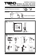
Installation Instructions TB/TS/KO, /OS, /KOS, /KOF, /KOSF
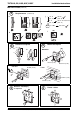
INSTALLATION (continued)
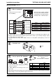
Wire to controller
7
* For /KO or /KOF connect Status/Power to 10 Vdc or 24 Vdc; if using /KOS, /OS, /KOSF as /KO
or /KOF, the Status/Power input should be powered from 10 Vdc e.g. via dummy analogue output.
** For /OS option also connect knob.
*** Note that /KO, /OS, /KOS, /KOF, /KOSF cannot be used by IQ211 (although they can be used
by IQ212)
IQ Configuration Manual
90-1533
TB/TS Data Sheet TA200603
Set up special IQ strategies
9
I Q
I Q
or
For /KO, /OS, /KOS, /KOF, /KOSF special override
and status strategies.
For /KOF, /KOSF special strategy for fan speed
input on IQs
dnegeLnoitisophctiwS
egatloV
lanimoNdednemmoceR
ffOnaFV0
deepswolnaFV8.2V2>
deepsmuidemnaFV6.5V5.4>
deepshgihnaFV5.
8V7>
citamotuAV7.9V9>
0 V
Temperature
Status/Power
Knob
+24 V
Fan
1
2
4
3
5
6
IN
OUT
0 V
IN
COM (0 V)
+24 V
IN
COM (0 V)
SENSOR
IQ
TB/TS
/K, /O
/S
/F
linked for thermistor (T)
analogue input
auxiliary supply
COM (0V)
analogue output
analogue input
see note ** below
analogue input
linked for thermistor (T)
linked for voltage (V)
linked for voltage (V)
1 2 3 4 5 6
LK1
LK2
Note that these options (TB/TS/
KO, /OS, /KOF, /KOSF) cannot be
used with IQLs; use options TB/TS,
TB/TS/K, /KE, or /KEF with IQLs.
NOITPOSLANIMRETTCENNOC
ST/BT2,1
K/ST/BT3,2,1
***OK/ST/BT*4,3,2,1
***SO/ST/BT4,**3,2,1
***SOK/ST/BT4,3,2,1
***FOK/
ST/BT6,5,*4,3,2,1
***FSOK/ST/BT6,5,4,3,2,1
Terminal size 0.5 to 2.5 mm
2
(14 to 20 AWG)
Note that the IQ recommended limits may need to be changed to suit mains supply voltage and auxiliary
supply loading, or a 24 Vdc regulated supply can be used.
Assemble unit
8
‘click’