TW100-W1CA IP Sharing for Cable Modem/xDSL User Manual M73-APO07-080
FCC Certifications This equipment has been tested and found to comply with the limits for a Class B digital device, pursuant to Part 15 of the FCC Rules. These limits are designed to provide reasonable protection against harmful interference in a residential installation. This equipment generates, uses and can radiate radio frequency energy and, if not installed and used in accordance with the instructions, may cause harmful interference to radio communications.
TABLE OF CONTENT INTROUCTION.......................................................................................................................................1 SAMPLE A PPLICATION ..................................................................................................................... 1 FEATURES............................................................................................................................................. 2 PARTS NAMES AND FUNCTIONS..............................
PERFORMING FIRMWARE UPGRADE .............................................................................................. 28 CHANGING PASSWORD..................................................................................................................31 FOR GUI.............................................................................................................................................. 31 FOR TERMINAL.......................................................................................
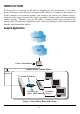
INTROUCTION IP Share device is designed for IP address simplification and conservation, as it enables private IP Internet works that use non-registered IP addresses to connect to the Internet. It usually connects two networks together, and translates the private (not globally unique) addresses in the internal network into single legal address before packets are forwarded onto another network. Therefore, only one IP address is needed for the entire network to the outside world.
Features ?? Supports PPPoE. ?? Supports VPN.(PPTP pass through). ?? Explicit LED indication for Internet connection. ?? Supports Internet applications such as Web, ICQ, FTP, Telnet, E-Mail, News, NetMeeting, PCAnyWhere, mIRC , CuSeeMe, AoE,… ?? Natural firewall keeps hackers out. ?? DHCP server allocates up to 128 client IP addresses. ?? DHCP client gets global IP address automatically. ?? 10/100Mbps dual speed auto-sensing for flexible network connectivity. ?? Virtual server. ?? Rich packet filters.
LED Color Indicator ? Power Status Glowing Green ? Local Link Green Dim Flashing Power On Power Off N/A. Connected to a LAN device Disconnected from any LAN device Receiving/ Sending data ? Local 100/10 Green 100Mbps detected 10Mbps detected N/A. ? Local Full/Half Green Full duplex Half duplex N/A.
System Requirements Your system must meet the following requirements to use the product’s Setup program. If you are using a Unix or apple based system, telnet should be used to configure the product. This product's GUI setup interface requires 1. Windows 95, 98, ME, NT or 2000. 2. IE4.01 or above well-installed. Telnet and Terminal setup are operating system independent.
FACTORY DEFAULT SETTINGS Password The default setting for password has been left blank in the factory. Press Enter then you are logged in for the first time. It is recommended that you set a password for security and management purpose. If you ever forget the password to log in, you can only reset the factory setting. Refer to the next section titled “Factory Reset” for details. Local and Global Port Addresses The LAN parameters of the product are pre-set in the factory. The default values are shown below.
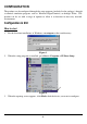
CONFIGURATION The product can be configured through the setup program (included in the package), through a terminal emulation program, such as Windows HyperTerminal, or through Telnet. The product can be set with a range of options to allow it to function in most any network environment. Configuration in GUI How to start 1. For the first time installation, in Windows, run setup.exe at the root directory. Figure 3 2. When the setup program is installed, go to Start? Programs ? IP Share Setup. 3.
Figure 5 Select the device that you would like to setup and then click Configure. Figure 6 The configure dialog box is categorized into several tabs as shown in the following.
Firmware Version: Read-only. Device/Computer Name: For you to enter a descriptive name for identification purpose. Some Internet Service Providers (ISP) requires this information. The Maximum input for this field is 20 alphanumeric characters and it is case sensitive. Domain Name 2: For example: yourcompany.com. The maximum input for this field is 32 alphanumeric characters and it is case insensitive.
TELNET management…: Checking this item lets you manage this device remotely from outside of the network through Telnet. ?? Default: disabled. Local Port This screen contains settings for LAN interface attached to the local network. Figure 8 IP Address ?? Default: 192.168.1.254 SubNetmask ?? Default: 255.255.255.0 ?Do not distribute IP address to local computers 3 Checking this radio button to disable this IP Sharing device to distribute IP Addresses.
Continuous IP address pool starts at The starting address of this local IP network address pool. The pool is a piece of continous IP address segment. Number of IP address in pool ?? Maximum: 128. Default: 128 Global Port This screen contains settings for the Global interface toward Internet. Figure 9 Adapter Address: Read-only. It is necessary for some ISP to identify this device by its MAC address.
SubNetmask4: Provided by our ISP. Gateway/DNS server #1/DNS server #2: These values will be automatically provided once you click “Obtain global port configuration automatically”. You can change the values if necessary. Virtual Server Being a natural Internet firewall, this IP Sharing device protects your network from being accessed by outside users. When there is application that requires outside users to access internal servers (e.g.
Figure 11 Port Type: please select the port type (TCP or UDP) for the port number that was entered earlier. Note: Maximum 12 Server Entries is allowed. Each port number can only be assigned to one IP address. Packet Filters In the Packet Filters setup screen, you can block specific internal users from accessing the Internet and you can also disable specific Internet services. You can set up the filters through the following three types of filter.
Figure 12 Network Adapter Address Filter: Filter according to local computer’s network adapter MAC address. Figure 13 Network Adapter’s MAC address consists of 12 alphanumeric characters (i.e. 00 ab 12 cd 34 ef) and it is normally printed on a sticker on the network adapter. If you have Windows 95, 98, or 98Me, go to “Start”, select “Run”, and type in winipcfg. Select the “network adapter” and you can find the Physical Address on the screen.
Remote IP: Filter using the IP address of a remote server (i.e. Web Server). Figure 14 TCP/UDP Port Filter TCP port: filter according to the Connection-Based Application Service on the remote server using the port number. UDP port: filter according to the Connectionless Application Service on the remote server using the port number. Figure 15 When you have finished setting the filters, the added filters will appear on the Filter List.
Configuration in Terminal Program Mode You can use terminal emulation on your PC/workstation for the initial and future configuration of your product. Windows HyperTerminal or other terminal emulation applications can be used. If you prefer, a telnet session can be opened directly. Telnet provides the same type of terminal emulation. For security purposes, the product uses port 333 for telnet.
Figure 18: COM 1 Properties 8. Power up the product. How to start Telnet 1. The instructions below are for using this unit at its default settings (i.e. DHCP enabled, Local Port IP address: 192.168.1.254, Subnet: 255.255.255.0). 2. Go to Start?Run. Figure 19 3. Type “telnet 192.168.1.254 333” and click on OK. If the local port’s IP address was set to something other than the factory default (“192.168.1.254”), enter that IP address.
333 Figure 20 Starting the Configuration 1. Once the connection is made successfully either via HyperTerminal or Telnet, the following information will appear, Dual Ethernet IP Share for Cable/xDSL Modem, version X.XX Administrator password: 2. No password is required the first time you log in. Press to enter Configure mode. The screen prompts you for the following command. command> 3. Type ? and hit “Enter” for a list of the commands.
TERMINAL COMMAND Type ? or help to list the main menu commands as below. command>help Dual Ethernet IP Share for Cable/xDSL Modem, version X.XX ======================================================= Command Description ------------------------------------------------------help Show this message session List active internet sessions show Display active configuration user List active local IP address leases filter Set packet filters passwd Change administrator's password ping
?? At command>, type in passwd and hit “Enter” to enter the password setup screen. ?? Password can be up to six characters long. ?? Password can contain letters, numbers, and spaces. ?? Password is case sensitive. ?? To set or change your password, key in up to six characters and hit “Enter”. You will be prompted to reenter your password for verification. Return to the Start screen by typing quit. ?? Test your new password to verify it has taken effect.
Obtain global port configuration from ISP : [Yes] .. under claiming IP address of global port : [0.0.0.0] SubNetmask of global port : [0.0.0.0] Device name : [Untitled] Domain name : [Domain] Gateway : [0.0.0.0] Primary DNS server : [0.0.0.0] Secondary DNS server : [0.0.0.0] set After executing the set command, the current settings will appear on the screen one at a time. Press Enter to accept the current value in the bracket or input new value and then press Enter to change the value.
SubNetmask of global port [0.0.0.0] : Device name (0 to 20 characters) [Untitled] : Domain name (0 to 36 characters) [Domain] : Gateway [0.0.0.0] : Primary DNS server [0.0.0.0] : Secondary DNS server [0.0.0.0] : New configuration will be: IP address of local port : [192.168.1.254] SubNetmask of local port : [255.255.255.0] Distribute IP addresses to local computers : [Yes] Continuous IP address pool starts at : [192.168.1.
Internet to the local network are blocked. Computers outside the Intranet are allowed to access specific ports by using the vserv command. There are four operation choices for vserv command: 1) Show, 2) Add, 3) Del, 0) Quit. Example: command>vserv Set local virtual server mapping (maximum 12), or to escape Operations => 1)Show 2)Add 3)Del 0)Quit : 2 Port number/application name : 80 ? Add a virtual server ? it's a Web server Type => 1)tcp 2)udp : 1 ? select TCP port Server IP address : 192.168.0.
command>release Give up the obtained global port configuration Note: if you choose NOT to obtain the global port configuration from your ISP, this command won’t be executed and the following message will appear. command>release Works only if 'Obtain global port configuration from ISP' is enabled renew You must renew the global port configuration after you have released it. Otherwise the device is disabled. The ‘Show’ command enables you to see the configuration.
192.168.10.4 0080-C8F8-8A64 2:55:48 Victoria 192.168.10.5 0080-C8F8-8A64 expired SNL Total 5 user, 3 active lease. Elapsed 0:01:03 Ping Ping is a basic Internet program that lets you verify that a particular IP address exists and can accept requests. At command> type in ping and then the IP address that you wish to detect. If the screen shows “reply ok!” from that IP, the device can communicate with that IP address. If the screen shows “no response!”, that IP address is unreachable.
tcp 7 GERNERAL 192.168.10.31 1033 4138 211.75.84.154 80 0 tcp 7 GERNERAL 192.168.10.32 1729 4139 140.113.39.195 110 0 1063 4140 210.66.41.132 110 0 tcp 7 GERNERAL 192.168.10.27 udp 1 GERNERAL 192.168.10.31 1028 16385 168.95.192.1 udp 1 GERNERAL 192.168.10.32 1726 16386 168.95.1.1 udp 1 GERNERAL 192.168.10.32 Active >> TCP:5,UDP:3 1728 16387 168.95.192.1 53 20 53 5 53 5 (Maximum >> TCP:128,UDP:64) filter This device supports three types of filter.
Item Type Action ==== ====== ======= 1. MAC Filter From To ================ ================ 0080C8123456 IP address filter: Example 1: Set IP address filter to allow those local computers with IP address from 192.168.0.25 to 192.168.0.32 to access Internet. Operations => 1)Show 2)Add 3)Del 0)Quit 2 Filter Type => 1)MAC 2)LAN IP 3)WAN IP 4)TCP 5)UDP 2 filter on IP address of local computers. Action => 1)Forward 2)Filter 1 pass on match IP Address (x.x.x.x): 192.168.0.25-192.168.0.
With the combination of the above two filter examples, the workstations with IP address 192.168.0.25, 192.168.0.26, 192.168.0.27, … and 192.168.0.32 can access the Internet via the Internet Router, but none of the workstations can access the 203.66.99.100 Web Server (web site). Port Filter Example 1: Allow users to access Web service only.
FIRMWARE UPGRADE System Requirements ?? One free COM port on PC. ?? A pin-to-pin RS-232 cable. One end is 9 pin male connector, the other end is 9 or 25 pin female connector depends on the COM port. ?? FWLOAD.EXE : This is an auxiliary program for firmware upload. ?? FIRMWARE.BIN : This is a firmware image file. ?? LOAD.EXE: This is the main program. The above three files MUST reside in the same subdirectory.
Figure 22 5. When the following screen appears, power on the device. Figure 23 6. Expect to wait for a few seconds before the upload program detects the device. Once the device is detected, the program will start uploading the firmware automatically. The upload process takes a couple of minutes. After the upload is completed, this device will automatically restart. Note: DO NOT interrupt the firmware uploading process. 7. When the upload finished, the screen should look like Figure 24 below.
- 30 -
CHANGING PASSWORD The device has no password at default. It is recommended that you change the default passwords to ensure that someone cannot adjust the devices settings. Using GUI 1. Start this device by running setup.exe as described in the chapter titled “Configuration”. 2. Check “Change Administrator’s Password. 3. Enter the desired new password in “New Password”. Enter the new password again in the “Confirm New Password” field. Please note that the password is case sensitive.
Note: In default, there is no password, so just leave this entry blank and hit “Enter” to continue. type new password (0 to 6 characters) : ****** Type in the new password and press re-type new password (0 to 6 characters) : ****** Re-type the new password and press Forgot your password? Refer to FAQ section for “Factory Reset” procedures.
PPP OVER ETHERNET (PPPOE) What is PPPoE? PPPoE is known as a dial-up DSL service. It is designed to integrate the broadband services into the current widely deployed, easy-to-use, and low-cost dial-up-access networking infrastructure. Thus, customer can get greater access speed without changing the operation concept. How can I know I am using PPPoE? A PPPoE client software provided by our ISP should be installed onto your computer first.
FAQ Factory Reset If for any reason, e.g. password being forgotten, you have to reset this device to factory default settings. By performing the Factory Reset, the current settings will be lost and the settings are reseted to default. The fctory default values is detailed in the section Factory Default Settings. Figure 26 “I can't find the product using the GUI Setup Software” For the GUI Setup Software to find the device, it has to be accessed from a client.
addresses on a LAN with an existing DHCP server may cause problems throughout a network. It is recommended you disable other DHCP serves on the network if you plan on using this product on the network. IP address conflict When you see the message box prompted for IP address conflict, this means two or more workstations has the same IP address. If you have setup the device as a DHCP server, please run the "winipcfg" utility to “release” all current configuration first, then “renew” the IP information again.
Figure 27 B. Choose the "Virtual Server" tab: C. Enter one of the port numbers that your application requires and press "Browse". Figure 28 D. Choose the computer that is using the application and press "Select". Note: If you know the IP address of the computer that is using this application, you can enter it in the “Local Server” and then click “add”.
Figure 29 E. Press Add. Repeat this process for each individual port you need to open.
F. Press Save. Wait 30 seconds for the device to reboot and then try the application again. It may be necessary to restart your application or your computer for the application to recognize the change. Can not access the Internet For Cable Modem users, find the workstation’s “Computer” name and then input this name in the device’s “Device/Computer Name” field. 1. On the Workstation (95, 98, and 98Me), go to Start ?Control Panel ? Network, and select Identification tab.
Figure 32 Check the physical connectivity of local network. Check if both the LEDs of Local and Global on the product’s front panel are green. If yes, go to next step. Otherwise, make sure you are using the correct cables and the cables are connected to the network devices properly. Check the physical connectivity of the broadband device. Examine the LED of LAN port and the LED of the broadband signal input on the Cable Modem/xDSL Modem.
Diagnosis TCP/IP Network Diagnosis Execute WINIPCFG.EXE or PING.EXE for TCP/IP network diagnosis. WINIPCFG The WINIPCFG program (for Win95, 98, and 98Me) is used to gather information about the TCP/IP connections that are active on your system. It cannot be used to dynamically adjust TCP/IP connections. You can also renew leases (if allowed by the network), and get the current IP address assignments through this program. From Windows, go to Start, click Run, enter WINIPCFG, and click OK.
Click here to reveal more. Figure 35: IP Configuration On the top, the “Host Name” and “DNS server” of the computer are configured to call when it is looking for a named resource. The default gateway is the server through which the client connects to the Internet. The DHCP Server identifies the network server that assigns IP addresses to computers on the network.
For example, to find the server 168.95.192.1, type the following command at the MS-DOS prompt: C:\>ping 168.95.192.1. PING can be executed in Windows as shown below: 1. Go to the Start menu. 2. Click Run. 3. Type ping 168.95.192.1 and click OK. 4. The server (IP address) is online if the following message appears. Reply from 192.168.0.1: bytes=32 time=3ms TTL=100 5. The destination device is not reachable if the following message appears. Reply from 192.168.0.1: Destination host unreachable.
Getting Technical Support You can also contact us for technical support. TRENDware www.trendware.com E-mail: techsupport@trendware.
APPENDIX A SPECIFICATIONS Protocols IP, NAT, ARP, ICMP, DHCP Management/Setup Locally, via direct serial cable connection through Console port Options Locally, via GUI for Windows 95/98/NT Remotely via Telnet (needs to enabled this function via GUI ) Local Port RJ-45, 10/100 Dual Speed Ethernet Global Port RJ-45, 10Mb Ethernet to an external Cable/DSL Modem Console Port DB-9 female connector LED Indicators Power, Local Link, Local Speed 10/100, Local Full/Half Duplex, Internet Link, Error Input
APPENDIX B SUPPORTED INTERNET APPLICATIONS Application Settings for Outgoing Connection Setting for Incoming connection ICQ98a,99b None None Netmeeting 2.1 None & 3.