FCC Warning UL Warning This equipment has been tested and found to comply with the regulations for a Class A digital device, pursuant to Part 15 of the FCC Rules. These limits are designed to provide reasonable protection against harmful interference when the equipment is operated in a commercial environment. This equipment generates, uses, and can radiate radio frequency energy and, if not installed and used in accordance with this user’s guide, may cause harmful interference to radio communications.
TABLE OF CONTENT About This Guide................................................................................. 1 Purpose ............................................................................................ 1 Terms/Usage .................................................................................... 1 Introduction.......................................................................................... 3 Gigabit Ethernet Technology ...........................................................
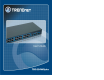
ABOUT THIS GUIDE Congratulations on your purchase of the 26-Port 10/100/1000Mbps Gigabit Ethernet Web Smart Switch. This device integrates 1000Mbps Gigabit Ethernet, 100Mbps Fast Ethernet and 10Mbps Ethernet network capabilities in a highly flexible package. Purpose This guide discusses how to install your 26-Port 10/100/1000Mbps Gigabit Ethernet Web Smart Switch.
INTRODUCTION This chapter describes the features of the 26-Port 10/100/1000Mbps Gigabit Ethernet Web Smart Switch and some background information about Ethernet/Fast Ethernet/Gigabit Ethernet switching technology. Gigabit Ethernet Technology Gigabit Ethernet is an extension of IEEE 802.
Switching Technology VLAN (Virtual Local Area Network) Another approach to pushing beyond the limits of Ethernet technology is the development of switching technology. A switch bridges Ethernet packets at the MAC address level of the Ethernet protocol transmitting among connected Ethernet or Fast Ethernet LAN segments. A VLAN is a group of end-stations that are not constrained by their physical location and can communicate as if a common broadcast domain, a LAN.
Up to 8K unicast addresses entities per device, self-learning, and table aging 256Kbytes packet buffer Supports IEEE 802.3x flow control for full-duplex mode ports Supports Back-pressure flow control for half-duplex mode ports Supports Port-based VLAN Supports Port-based QoS / IEEE 802.
UNPACKING AND INSTALLATION This chapter provides unpacking and installation information for the Switch. Unpacking Open the shipping cartons of the Switch and carefully unpacks its contents. The carton should contain the following items: One 26-Port 10/100/1000Mbps Gigabit Web Smart Switch One Multi-Language Quick Installation Guide One Utility/User’s Guide CD-ROM Install the Switch on a sturdy, level surface that can support its weight, or in an EIA standard-size equipment rack.
Connecting Network Cable The Switch supports 10Mbps Ethernet or 100Mbps Fast Ethernet and it runs both in half and full duplex mode using two pair of Category 5 cable. The Switch also supports 2-Ports 1000Mbps Gigabit Ethernet that runs in Auto-negotiation mode and 10Mbps Ethernet or 100Mbps Fast Ethernet that runs both in half and full duplex mode and 1000Mbps Gigabit Ethernet runs in full duplex mode using four pair of Category 5 Cable. These RJ45 ports are Auto-MDI type port.
IDENTIFYING EXTERNAL COMPONENTS This chapter describes the front panel, rear panel, and LED indicators of the Switch. Front Panel The figure below shows the front panels of the Switch. mini-GBIC Ports (Port 25~26): The Switch is equipped with two mini-GBIC ports, supported optional 1000BASE-SX/LX mini-GBIC module. Port 25 and 26 are the same ports with the mini-GBIC no.25 and 26 ports, when plug in the mini-GBIC module, the device will activate mini-GBIC, and the RJ45 port will be disabled.
UNDERSTANDING LED INDICATORS Ports 1~24 10/100M Status LEDs The front panel LEDs provides instant status feedback, and, helps monitor and troubleshoot when needed. Link/ACT: Link/Activity On : When the Link/ACT LED lights on, the respective port is successfully connected to an Ethernet network. Blinking : When the Link/ACT LED is blinking, the port is transmitting or receiving data on the Ethernet network. Off : No link. Figure 5.
1000Mbps On Off CONFIGURATION : When the 1000Mbps LED lights on, the respective port is connected to a 1000Mbps Gigabit Ethernet network. : When the respective port is connected to a 10Mbps Ethernet or 100Mbps Fast Ethernet network 100Mbps On : When the 100Mbps LED lights on, the respective port is connected to a 100Mbps Fast Ethernet network. Off : When the respective port is connected to a 10Mbps Ethernet or 1000Mbps Gigabit Ethernet network.
System word definitions in the Discovery List: z z z z z z z z z MAC Address: Shows the device MAC Address. IP Address: Shows the current IP address of the device. Protocol version: Shows the version of the Utility protocol. Product Name: Shows the device product name. System Name: Shows the appointed device system name. Location: Shows where the device is located. Trap IP: Shows the IP where the Trap to be sent. Subnet Mask: Shows the Subnet Mask set of the device.
View Trap: The Trap function can receive the events that happen from the Web Management Switch in the Monitor List. There is a light indicator behind the “View Trap” button, when the light indicates in green, it means that there is no trap transmitted, and else when it indicates in red, it means that there is new trap transmitted, this is to remind us to view the trap. (Figure 7) Figure 7.
Firmware Upgrade: When the device has a new function, there will be a new firmware to update the device, use this function to update. In the “View TAB”, there are view log and clear log function, this function will help you to show trap setting. View Log: To show the event of the Web Management Utility and the device. Clear Log: to clear the log. In the “Option TAB”, there are Refresh Time function, this function helps you to refresh the time of monitoring the device.
After entering the password, the main page comes up, the screen will display the device status. Login Before you configure this device, note that when the Web Smart Switch is configured through an Ethernet connection, make sure the manager PC must be set on same the IP network. For example, when the default network address of the default IP address of the Web Smart Switch is 192.168.0.1, then the manager PC should be set at 192.168.0.
Setup Menu Configuring Setup Setting When the main page appears, find the Setup menu in the left side of the screen (Figure 15). Click on the setup item that you want to configure. There are eleven options: Port Settings, VLAN Settings, Trunk Setting, Mirror Setting, QoS Setting, Device Status, System Settings, Trap Setting, Password Setting, Backup Setting and Reset Setting as shown in the Main Menu screen.
To change the port setting, click on the ID parameter to enter to the selected port to configure its Speed/Disable, Flow control and Port Bandwidth Rate Control Ingress and Egress. VLAN Settings (Virtual Local Area Network) Group individual ports into a small “Virtual” network of their own to be independent of the other ports.
Trunk Setting Mirror Setting The Trunk function enables to cascade two or more devices with a larger bandwidths. There are three Trunking groups to be set; and there are default ports in each member. Checked “Enable” to use the trunk function, select the ports in each member to be trunk, and click “Apply” to activate the selected trunk group.
QoS Setting Device Status There are two selections in QoS setting, Port Based and IEEE 802.1p Based. Click on the “Status” to present the device status on this screen, it will show the System Status, Port Status, VLAN Status, Trunk Status and Mirror Status. Figure 22. Port Based: to set the Switch QoS by port based, select the ports which need to higher the quality by changing Normal to High. Figure 23. IEEE 802.1p Based: to set the Switch QoS based on IEEE 802.1p, Figure 25.
System Setting Trap Setting The System Setting includes the System name, Location name, Login Timeout, IP Address, Subnet Mask and Gateway. Through the Web Management Utility, you can easily recognize the device by using the System Name and the Location Name. The Trap Setting enables the device to monitor the Trap through the Web Management Utility, set the Trap IP Address of the manager where the trap to be sent.
Set Password Reset Setting Password is the invaluable tool for the manager to secure Web Management Switch, use this function to change the password. If you forget the password, press the “Reset” button in the rear panel of the Switch, the current setting includes VLAN, Port Setting… etc. will be lost and the Switch will restore to the default setting. The Factory Reset button helps you to reset the device back to the default setting from the factory.
TECHNICAL SPECIFICATIONS General Standards IEEE 802.3 10Base-T Performance Transmits Method: Store-and-forward Filtering Table: 8K entries per device Address IEEE 802.3u 100Base-TX IEEE 802.3ab 1000Base-T IEEE 802.3z 1000Base-SX/LX (Mini-GBIC) Packet Filtering/Forwarding Rate: IEEE 802.
Limited Warranty (iii) the product was subject to conditions more severe than those specified in the manual. TRENDware warrants its products against defects in material and workmanship, under normal use and service, for the following lengths of time from the date of purchase. Warranty service may be obtained by contacting TRENDware office within the applicable warranty period for a Return Material Authorization (RMA) number, accompanied by a copy of the dated proof of the purchase.
PERSON’S MISUSE, NEGLECT, IMPROPER INSTALLATION OR TESTING, UNAUTHORIZED ATTEMPTS TO REPAIR OR MODIFY, OR ANY OTHER CAUSE BEYOND THE RANGE OF THE INTENDED USE, OR BY ACCIDENT, FIRE, LIGHTNING, OR OTHER HAZARD.