Table of Contents 1 English 1. Before You Start 2. Hardware Setup and Configuration 3.
1.
2. Hardware Setup and Configuration Note: *The default IP address of the TEW-740APBO Is 192.168.10.100. To configure the TEW-740APEO, your network adapter must have an IP address within the 192.188.10x subset {.g. 192.168.10.10). Please refer to the Appendix In the User's Gilda for more Information. +The initial configuration should be completed in a testing environment with two TEW-740APBO access points approximately apart from one anther with the front of the access points directly facing each other.
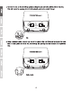
1. Remove the cover of the access penman by pulling and holding the tab in the vertical direction upward (based on the access point orientation below} and siding the cover In the two locations noted below away from the access point. Pull and hold tab 2. Write down the MAC address (WiFi MAC) of the TEW-740APBO #1 access port. The MAC address (WIF MAC) can be found on the Inside of the device cover where the Ethernet LAN Ports are located (shown below).
3. Removal the tab on the far left by gentry bending It back and forth until the tab I8 removed. ‘This wil crests the opening for a R-45 network cabs to ba routed through. 4, Using a network cabs, connect one end of the cable to the LAN (Po} port and push the cable Into the cable guide on the far left, then through the opening that was created In the previous step.
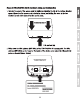
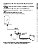
5. Connect the other end of the network cable to the P+DATA OUT port on the included PoE Injector. 6. Using another network cable, connect one end to the 10/100 DATA IN port on the Included PoE Injector. 7. Conn est the other end of the network cable to your computer's Theme port. 8. Connect the Included power adapter to the POE Injector POWER I on the Included PoE injector. 9, Plug the connected power adapter Into a power outlet. 10. Confirm the device ls powered on through the LED Indicators.
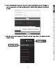
12. Open your web browser and type the IP address of the access point In the address bar, then press Enter. The default IP address Is 192.168.10.100. pith /102168 10,100 When prompted, login to the browser configuration page using the default user name and password settings. User Name: admin Password: admin M Note: User Name and Password ars case sensitive. B 14. Click on the System tab and select Management.
15, Under Administrator Password, change the default administrator password by typing in Your newt password In the fields provided and then slick the Save button at the bottom of the page. Esn Please Reboot Device 16. Afar the device saves changes and reboots, In the top many, click on the System and click 'on Mode Setup.
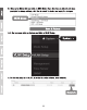
17. Click on the Soda fled and click on WDS Mode. Then click Save & Reboot and when prompted to change settings, click Yes to reboot the device and apply the changes. the top menu, click on System and click on DYLAN Setup. B 19. For the first entry In the CLAN List under the action column, click Network.
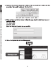
20. In the IP Setup section, enter the IP Address 192.168.10.50 and Net mask 255.255.255.0. ‘Then click Save. In the many located at the top, you will be prompted to reboot the advice. Click the Reboot button and In the following page, click Reboot. When prompted to change settings, click Yes o reboot the device and apply the changes. Mote: When configuring TEW-740APBO #2, enter the IP address settings 192.163.10.51 and Net mask 255.255.255.0. e hes = Elam pita 1 Dress L e Her mask | ARLENE 21.
22, Click on the Wireless tab and select WDS Setup. LR 23, Click Enabled for the WDS Setup and under Authentication, select AES. Enter a WDS Pass Phrase (8-63 alphanumeric characters). Noe: When configuring TEW-740APBO Unit #2, the WDS AES Passphrase must be the same as TEW-740ABPO Under WDS Cl lent Setup, sack the first entry and enter the WIF MAC address of TEW-740APBO #2. Then click Save. Iota: When configuring the TEW-740APBO #2, enter the WiFi MAC address of TEW-740APBO #1.
25, When prompted, click Reboot at the top of the page, click the Reboot button, and click Yes to reboot and apply the configuration changes. Nike: After the device reboots and applies changes, you will need to reconnect to device configuration page using the new IP address settings. Phase 3: TEW-740APBO Unit #2 Hardware and ration When configuring the TEW-740APBO #2, repeat all of the steps in Phase 2 setup and configuration. 1. In Step 12 and 20, under IP Setup, stern the IP Address 192.168.10.
Phase 4 Confirm Connectivity 1. Leave your computer connected to TEW-740APBO #2 and keep the web management Interface open. 2. Make sure both TEW-740APBO #1 and TEW-740APBO 2 access points are sporadic on approximately apart from one another with front of access points directly facing each other.
3. To verify connectivity, in the TEN-740ABPO #2 web management interface, click on Utility and click on Network Uiy, Network Utility 4. In the Somalian field, terrier the IP address of TEW-74QAPE0 then next 1o Times, click Ping. Ping replies and 0% packs loss will Indicate as successful point to point bridge connection between the TEW-740APBO #1 and #2. Note: If the connectivity test falls, Walt for about a minus and try again.
3. Ground Wire and Pole Mount Installation 1. Locate the grounding point located in the bosom section of the enclosure, Using a Phillips ‘screwdriver, removal the grounding port screw (counter clockwise) and attach the Included grounding wire to the grounding point screw. Reattach the ground screw {clockwise) along with the grounding wire. After installing the grounding wire, remove snottier tab on the enclosure by gently bending back and forth until the tab Is removed.
2. Re-Install the cover by lining up the guldens Info the notches as shown and push the cover down until the cover cps In and s secure. After reinstalling the cover, Insert the Included rubber seal in opening as show. 1 = 3. Inge rt the Included fasteners through the holes located at the back of the access point. Wrap the fasteners around the pole where the access points will be installed. On the fasteners, Insert the open end Ito the locking mechanism and pull tight url the access point Is secured. 5.
FCL Statement ‘This equipment has been tested and found 1o comply with the limits for a Class B digital device, pursuant to part 15 of the FCC Rules. Thea limits ars designed to provide reasonable protection against harmful Interference In a residential Installation. This equipment generates, uses and can radiate radio frequency energy and, if not installed and used in accordance with the instructions, may cause harmful interference to radio communications.